
Datasheet


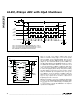

If you read the data bits between conversions, you can:
1) count CLK cycles until the end of the conversion, or
2) poll EOC to determine when the conversion is
finished, or
3) generate an interrupt on EOC’s falling edge.
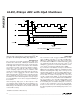
Note that the MSB conversion result appears at DOUT
after CS goes low, but before the first SCLK pulse.
Each subsequent SCLK pulse shifts out the next con-
version bit. The 15th SCLK pulse shifts out the LSB.
Additional clock pulses shift out zeros.
MAX195
16-Bit, 85ksps ADC with 10µA Shutdown
_______________________________________________________________________________________ 9
CLK
START
CONV
MAX195
CONV
START
CLK
SEE
DIGITAL INTERFACE
SECTION
CS
CONV
CLK
(CASE 1)
CLK
(CASE 2)
EOC
t
DV
t
CD
t
CW
t
CEH
CASE 1: CLK IDLES LOW, DATA LATCHED ON RISING EDGE (CPOL = 0, CPHA = 0)
CASE 2: CLK IDLES LOW, DATA LATCHED ON FALLING EDGE (CPOL = 0, CPHA = 1)
NOTE: ARROWS ON CLK TRANSITIONS INDICATE LATCHING EDGE
t
CEL
DOUT
t
DH
B15
CONVERSION
BEGINS
CONVERSION
ENDS
MSB
LSB
B14 B13 B12 B2 B1 B0 B15
B15 FROM PREVIOUS
CONVERSION
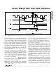
Figure 5. Gating CONV to Synchronize with CLK
Figure 6. Output Data Format, Reading Data During Conversion (Mode 1)