
Datasheet

MAX1870A
Step-Up/Step-Down
Li+ Battery Charger
______________________________________________________________________________________ 21
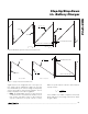
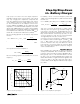
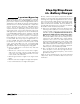
STATE B
STATE A
PRECALCULATED STEP-DOWN ON-TIME
VALLEY REGULATED OFF-TIME
dl
dt
V
IN
- V
OUT
L
=
dl
dt
V
OUT
L
=
V
IN
> 1.4 x V
BATT
DUTY = V
IN
/ V
OUT
Figure 6. MAX1870A Step-Down Inductor Current Waveform
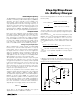
signal based on the integrated error of the input cur-
rent, charge current, and battery voltage. The error sig-
nal, determined by the lowest voltage clamp (LVC),
sets the threshold for current-mode regulation. The fol-
lowing comparators are used for regulation:
• IMIN: The MAX1870A operates in discontinuous
conduction if LVC is below 0.15V, and does not ini-
tiate another step-down on-time. In discontinuous
step-up conduction, the peak current is set by
IMIN. The peak inductor current in discontinuous
step-up mode is:
where VIMIN is the IMIN comparator threshold,
0.15V, and ACSI is the charge current-sense ampli-
fier gain, 18V/V.
I
V
AxRS
PK
IMIN
CSI
>
2
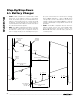
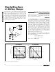
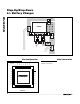
STATE B
STATE C
PRECALCULATED OFF-TIME
PEAK REGULATED ON-TIME
dl
dt
V
IN
- V
OUT
L
=
dl
dt
V
OUT
L
=
V
IN
> 0.9 x V
BATT
DUTY = 1 - V
IN
/ V
OUT
Figure 7. Step-Up Inductor-Current Waveform