
Datasheet


MAX1778/MAX1880–MAX1885
Quad-Output TFT LCD DC/DC
Converters with Buffer
27
Maxim Integrated
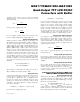
Rectifier Diode
Use a Schottky diode with an average current rating
equal to or greater than the peak inductor current, and
a voltage rating at least 1.5 times the main output volt-
age (V
MAIN
).
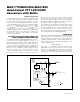
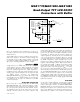
Charge Pumps (MAX1778/ MAX1880/
MAX1881/MAX1882 Only)
Selecting the Number of Charge-Pump Stages
The number of charge-pump stages required to regu-
late the output voltage depends on the supply voltage,
output voltage, load current, switching frequency, the
diode’s forward voltage drop, and ceramic capacitor
values.
For positive charge-pump outputs, the number of
required stages can be determined by:
where V
SUPD
is the positive charge-pump diode supply
(Figure 4), V
DIODE
is the diode’s forward voltage drop,
and R
TX
is the charge pump’s output impedance. The
charge pump’s output impedance can be approximat-
ed using the following equation:
where the charge pump’s switching frequency (f
CHP
) is
equal to 0.5 x f
OSC
, the p-channel MOSFET’s on-resis-
tance (R
PCH(ON)
) is 10Ω, and the n-channel MOSFET’s
on-resistance (R
NCH(ON
)) is 4Ω (see the
Electrical
Characteristics
).
For negative charge-pump outputs, the number of
required stages can be determined by:
where N
NEG
is rounded up to the nearest integer.
N
V
VVRI
NEG
NEG
SUPN DROP TX LOAD
.( )
≥
+
⎛
⎝
⎜
⎞
⎠
⎟
-112
RR R
Cf
Cf
TX PCH ON NCH ON
X CHP
OUT CHP
( )
() ()
=++
⎛
⎝
⎜
⎞
⎠
⎟
+
⎛
⎝
⎜
⎞
⎠
⎟
2
1
1
N
VV
VVRI
POS
POS SUPD
SUPP DIODE TX LOAD
.( )
≥
+
⎛
⎝
⎜
⎞
⎠
⎟
-
-112
CIRCUIT 1 CIRCUIT 2 CIRCUIT 3 CIRCUIT 4 CIRCUIT 5
V
IN
3.3V 3.3V 3.3V 5V 5V
V
MAIN
9V 9V 9V 12V 12V
I
MAIN(MAX)
100mA 200mA 200mA 220mA 220mA
V
NEG
-5V -5V -5V -5V -5V
I
NEG
2mA 5mA 5mA 5mA 5mA
V
POS
24V 24V 24V 24V 24V
I
POS
2mA 5mA 5mA 5mA 5mA
L 2.2µH 4.7µH 4.7µH 6.8µH 6.8µH
I
PEAK
>1A >1A >1A >1A >1A
C
OUT
4.7µF 10µF 20µF 10µF 20µF
R1 309kΩ 309kΩ 309kΩ 429kΩ 429kΩ
R2 49.9kΩ 49.9kΩ 49.9kΩ 49.9kΩ 49.9kΩ
R
COMP
None None 39kΩ* None 20kΩ*
C
COMP
None None 100pF* None 200pF*
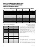
Table 1. MAX1778/MAX1880/MAX1883 Component Values (f
OSC
= 1MHz)
*R
COMP
and C
COMP
are connected between the step-up converter’s output (V
MAIN
) and FB.