
Datasheet


MAX1776
24V, 600mA Internal Switch, 100% Duty Cycle,
Step-Down Converter
Maxim cannot assume responsibility for use of any circuitry other than circuitry entirely embodied in a Maxim product. No circuit patent licenses are
implied. Maxim reserves the right to change the circuitry and specifications without notice at any time.
Maxim Integrated Products, 120 San Gabriel Drive, Sunnyvale, CA 94086 408-737-7600 ____________________ 13
© 2003 Maxim Integrated Products Printed USA is a registered trademark of Maxim Integrated Products.
Typical Application Circuit (Figure 1), should be as
short and wide as possible. Additionally, the current
loops formed by the power components (CIN, COUT,
L1, and D1) should be as short as possible to avoid
radiated noise. Connect the ground pins of these
power components at a common node in a star-ground
configuration. Separate the noisy traces, such as the
LX node, from the feedback network with grounded
copper. Furthermore, keep the extra copper on the
board and integrate it into a pseudo-ground plane.
When using external feedback, place the resistors as
close to the feedback pin as possible to minimize noise
coupling.
Chip Information
TRANSISTOR COUNT: 932
PROCESS: BiCMOS
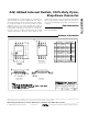
Package Information
8LUMAXD.EPS
PACKAGE OUTLINE, 8L uMAX/uSOP
1
1
21-0036
J
REV.DOCUMENT CONTROL NO.APPROVAL
PROPRIETARY INFORMATION
TITLE:
MAX
0.043
0.006
0.014
0.120
0.120
0.198
0.026
0.007
0.037
0.0207 BSC
0.0256 BSC
A2
A1
c
e
b
A
L
FRONT VIEW
SIDE VIEW
E H
0.6±0.1
0.6±0.1
ÿ 0.50±0.1
1
TOP VIEW
D
8
A2
0.030
BOTTOM VIEW
1
6∞
S
b
L
H
E
D
e
c
0∞
0.010
0.116
0.116
0.188
0.016
0.005
8
4X S
INCHES
-
A1
A
MIN
0.002
0.950.75
0.5250 BSC
0.25 0.36
2.95 3.05
2.95 3.05
4.78
0.41
0.65 BSC
5.03
0.66
6∞0∞
0.13 0.18
MAX
MIN
MILLIMETERS
- 1.10
0.05 0.15
α
α
DIM