
Datasheet


MAX1761
Small, Dual, High-Efficiency
Buck Controller for Notebooks
_______________________________________________________________________________________ 3
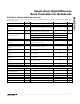
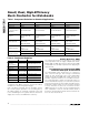
PARAMETER SYMBOL CONDITIONS MIN TYP MAX UNITS
FAULT PROTECTION
Output Undervoltage Threshold
(Foldback)
V
FB
,
UVFB
With respect to the regulation point, no load 60 70 80 %
Output Undervoltage Blanking
Time
V
FB
,
UVLO
(
t
)
Measured from ON_ signal going high 10 32 ms
GND - CS_, positive direction 92 100 108
GND - CS_, negative direction, ON2 = floating -135 -120 -105
Current-Limit Threshold
GND - CS_, zero crossing, ON2 = 5V 2.5
mV
Thermal Shutdown Threshold Hysteresis = 10
o
C 160
o
C
VL Undervoltage Lockout
Threshold
V
VL
,
UVLO
Rising edge, hysteresis = 20mV, PWM is
disabled below this voltage
4.1 4.4 V
GATE DRIVERS
DH_ Gate Driver On-Resistance
(Pullup)
V+ = 6V to 20V, DH_, high state 3.7 8 Ω
DH_ Gate Driver On-Resistance
(Pulldown)
DH_, low state 6.2 10 Ω
DL_ Gate Driver On-Resistance
(Pullup)
DL_ , high state 3.4 8 Ω
DL_ Gate Driver On-Resistance
(Pulldown)
DL_, low state 2.0 5 Ω
DH_ Gate Driver Source/Sink
Current
V
DH_
= 3V, V+ = 6V 0.6 A
DL_ Gate Drive Sink Current V
DL_
= 2.5V 0.9 A
DL_ Gate Drive Source Current V
DL_
= 2.5V 0.5 A
LOGIC CONTROLS
ON_ Logic Input High Voltage 2.05 V
ON2 Logic Input Float Voltage
(Forced-PWM Mode)
2.0V < V
ON1
< VL 1.3 1.7 1.95 V
ON_ Logic Input Low Voltage 0.5 V
ON1 Logic Input Current -1 1 µA
ON2 Logic High Input Current V
ON2
> 2.0V 0 1 3 µA
ON2 Logic Low Input Current V
ON2
< 0.5V, V
ON1
> 2.0V -2 -1 0 µA
FB_ Dual Mode Threshold 50 100 150 mV
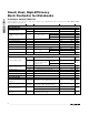
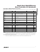
ELECTRICAL CHARACTERISTICS (continued)
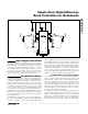
(Circuit of Figure 1, V+ = 15V, C
VL
= 4.7µF, C
REF
= 0.1µF, VL not externally driven unless otherwise noted, T
A
= 0°C to +85°C, unless
otherwise noted.) (Note 1)