
Datasheet


MAX1761
Small, Dual, High-Efficiency
Buck Controller for Notebooks
______________________________________________________________________________________ 11
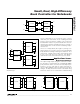
On-Time One-Shot
The heart of the PWM core is the one-shot that sets the
high-side switch on-time for both controllers. This fast,
low-jitter, adjustable one-shot includes circuitry that
varies the on-time in response to battery and output
voltage. The high-side switch on-time is inversely pro-
portional to the battery voltage as measured by the V+
input, and proportional to the output voltage. This algo-
rithm results in a nearly constant switching frequency
despite the absence of a fixed-frequency clock genera-
tor. The benefits of a constant switching frequency are
twofold: first, the switching noise occurs at a known fre-
quency and is easily filtered; second, the inductor rip-
ple current remains relatively constant, resulting in
predictable output voltage ripple and a relatively sim-
ple design procedure. The difference in frequencies
between OUT1 and OUT2 prevents audio-frequency
“beating” and minimizes crosstalk between the two
SMPS. The on-times can be calculated by using the
equation below that references the K values listed in
Table 3.
The 0.1V offset term accounts for the expected drop
across the low-side MOSFET switch.
On - Time = K
V + 0.1V
V
OUT_
IN
OUT1 OUT2
ON1 ON2
C
IN1
C
IN2
DL1
DL2
DL1 DL2
ZCC1
ZCC2
ILIM1
ILIM2
VOS
Q2
Q4
Q1
Q3
D1
D2
L1
L2
C
OUT1
C
OUT2
-0.1V -0.1V
PWM
CONTROL
BLOCK
PWM
CONTROL
BLOCK
LINEAR
REG
2V
V
REF
MAX1761
OUT1
VL
DH1
DH2
DH DH
DL DL
OUT OUT
GND
SHDN
V+
VL
REF
CS1
CS2
ILIM ILIM
ZERO
CROSSING
ZERO
CROSSING
DL1
DH2
ON1
DRIVER
DRIVER
DRIVER DRIVER
OUT1
V
IN
V
IN
C
L
C
REF
VL
V
IN
ON1
SHDN
V
IN
VL
REF
OUT2
ON2
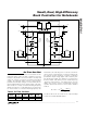
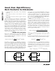
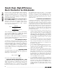
Figure 2. Functional Diagram
Table 3. On-Time One-Shot
DEVICE
K
(µs)
MIN
(kHz)
TYP
(kHz)
MAX
(kHz)
OUT1 2.857 318 350 428
OUT2 4.000 227 250 278