
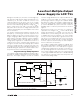
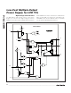
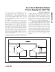
Datasheet

where I
AVDD
_
PEAK
is the peak inductor current (see the
Inductor Selection
section). For ceramic capacitors, the
output voltage ripple is typically dominated by
V
AVDD
_
RIPPLE(C)
. The voltage rating and temperature
characteristics of the output capacitor must also be
considered. Note that all ceramic capacitors typically
have large temperature coefficient and bias voltage
coefficients. The actual capacitor value in circuit is typi-
cally significantly less than the stated value.
Input Capacitor Selection
The input capacitor reduces the current peaks drawn
from the input supply and reduces noise injection into
the IC. A 22µF ceramic capacitor is used in the typical
operating circuit (Figure 1) because of the high source
impedance seen in typical lab setups. Actual applica-
tions usually have much lower source impedance since
the step-up regulator often runs directly from the output
of another regulated supply. Typically, the input capaci-
tance can be reduced below the values used in the typi-
cal operating circuit.
Rectifier Diode
The MAX17014’s high switching frequency demands a
high-speed rectifier. Schottky diodes are recommend-
ed for most applications because of their fast recovery
time and low forward voltage. In general, a 2A Schottky
diode complements the internal MOSFET well.
Output-Voltage Selection
The output voltage of the step-up regulator can be
adjusted by connecting a resistive voltage-divider from
the output (V
AVDD
) to GND with the center tap connect-
ed to FB1 (see Figure 1). Select R4 in the 10kΩ to 50kΩ
range. Calculate R3 with the following equation:
where V
FB1
, the step-up regulator’s feedback set point,
is 1.25V. Place R4 and R3 close to the IC.
Loop Compensation
Choose R
COMP
(R5 in Figure 1) to set the high-frequen-
cy integrator gain for fast transient response. Choose
C
COMP
(C17 in Figure 1) to set the integrator zero to
maintain loop stability.
For low-ESR output capacitors, use the following equa-
tions to obtain stable performance and good transient
response:
To further optimize transient response, vary R
COMP
in
20% steps and C
COMP
in 50% steps while observing
transient response waveforms.
Charge-Pump Regulators
Selecting the Number of Charge-Pump Stages
For highest efficiency, always choose the lowest number
of charge-pump stages that meet the output requirement.
The number of positive charge-pump stages is given by:
where n
POS
is the number of positive charge-pump
stages, V
GON
is the output of the positive charge-pump
regulator, V
SUP
is the supply voltage of the charge-
pump regulators, V
D
is the forward voltage drop of the
charge-pump diode, and V
DROPOUT
is the dropout
margin for the regulator. Use V
DROPOUT
= 300mV.
The number of negative charge-pump stages is given by:
where n
NEG
is the number of negative charge-pump
stages and V
GOFF
is the output of the negative charge-
pump regulator.
The above equations are derived based on the
assumption that the first stage of the positive charge
pump is connected to V
AVDD
and the first stage of the
negative charge pump is connected to ground.
Sometimes fractional stages are more desirable for bet-
ter efficiency. This can be done by connecting the first
stage to V
OUT
or another available supply. If the first
charge-pump stage is powered from V
OUT
, then the
above equations become:
n
VV V
VV
NEG
GOFF DROPOUT OUT
SUP D
=
−+ +
−×2
n
VV V
VV
POS
GON DROPOUT OUT
SUP D
=
+−
−×2
n
VV
VV
NEG
GOFF DROPOUT
SUP D
=
−+
−×2
n
VV V
VV
POS
GON DROPOUT AVDD
SUP D
=
+−
−×2
C
VC
IR
COMP
AVDD AVDD
AVDD MAX COMP
≈
×
××1250
()
R
VV C
LI
COMP
VIN AVDD AVDD
AVDD AVDD MAX
≈
×× ×
×
125
()
RR
V
V
AVDD
FB
34 1
1
=× −
⎛
⎝
⎜
⎞
⎠
⎟
MAX17014
Low-Cost Multiple-Output
Power Supply for LCD TVs
______________________________________________________________________________________ 29