
Datasheet
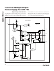

Select the first mode by connecting MODE to VL. When
CTL is logic-high, Q1 turns on and Q2 turns off, con-
necting GON to SRC. When CTL is logic-low, Q1 turns
off and Q2 turns on, connecting GON to DRN. GON
can then be discharged through a resistor connected
between DRN and GND or AV
DD
. Q2 turns off and
stops discharging GON when V
GON
reaches 10 times
the voltage on THR.
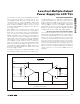
When V
MODE
is less than 0.8 x V
VL
, the switch control
block works in the second mode. The rising edge of
V
CTL
turns on Q1 and turns off Q2, connecting GON to
SRC. An internal n-channel MOSFET, Q3, between
MODE and GND is also turned on to discharge an
external capacitor between MODE and GND. The
falling edge of V
CTL
turns off Q3, and an internal 50µA
current source starts charging the MODE capacitor.
Once V
MODE
exceeds V
VL/4
, the switch control block
turns off Q1 and turns on Q2, connecting GON to DRN.
GON can then be discharged through a resisor con-
nected between DRN and GND or AV
DD
. Q2 turns off
and stops discharging GON when V
GON
reaches 10
times the voltage on THR.
The switch control block is disabled and DLP is held
low when EN1 or EN2 is low or the IC is in a fault state.
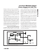
Operational Amplifiers
The MAX17014 has two operational amplifiers. The
operational amplifiers are typically used to drive the
LCD backplane (VCOM) or the gamma-correction
divider string. They feature ±150mA output short-circuit
current, 100V/µs slew rate, and 20MHz, -3dB band-
width. While the op amp is a rail-to-rail input and output
design, its accuracy is significantly degraded for input
voltages within 2V of its supply rails (OVIN, OGND).
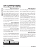
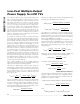
Short-Circuit Current Limit and Input Clamp
The operational amplifiers limit short-circuit current to
approximately ±150mA (-250mA) if the output is direct-
ly shorted to OVIN (OGND). If the short-circuit condition
persists, the junction temperature of the IC rises until it
reaches the thermal-shutdown threshold (+160°C typ).
Once the junction temperature reaches the thermal-
shutdown threshold, an internal thermal sensor immedi-
ately sets the thermal-fault latch, shutting off all the IC’s
outputs. The device remains inactive until the input volt-
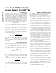
age is cycled. The operational amplifiers have 4V input
clamp structures in series with a 500Ω resistance
(Figure 6).
MAX17014
Low-Cost Multiple-Output
Power Supply for LCD TVs
______________________________________________________________________________________ 23
NEG1
POS1
OVIN
OUT1
NEG2
POS2
OUT2
OGND
OP AMP INPUT CLAMP STRUCTURE
500Ω
±4V
MAX17014
500Ω
±4V
Figure 6. Op Amp Input Clamp Structure