
Datasheet

MAX17014
High-Voltage Switch Control
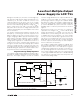
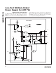
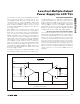
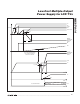
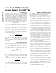
The MAX17014’s high-voltage switch control block
(Figure 5) consists of two high-voltage p-channel
MOSFETs: Q1, between SRC and GON and Q2, between
GON and DRN. The switch control block is enabled when
V
DLP
exceeds V
REF
. Q1 and Q2 are controlled by CTL
and MODE. There are two different modes of operation
(see the
Typical Operating Characteristics
).
Low-Cost Multiple-Output
Power Supply for LCD TVs
22 ______________________________________________________________________________________
MODE
CTL
DLP
SRC
GON
DRN
V
REF
SUI DONE
8μA
REF
Q1
Q4
Q3
R
2R
R
50μA
SWITCH CONTROL
THR
9R
R
VL
VL /2
1.25kΩ
SHDN
FAULT
Q5
MAX17014
6kΩ
Q2
Figure 5. Switch Control