
Datasheet

MAX17014
On the rising edge of the internal clock, the controller
sets a flip-flop, turning on the n-channel MOSFET and
applying the input voltage across the inductor. The cur-
rent through the inductor ramps up linearly, storing
energy in its magnetic field. Once the sum of the current-
feedback signal and the slope compensation exceed the
COMP voltage, the controller resets the flip-flop and turns
off the MOSFET. Since the inductor current is continuous,
a transverse potential develops across the inductor that
turns on the diode (D1). The voltage across the inductor
then becomes the difference between the output voltage
and the input voltage. This discharge condition forces
the current through the inductor to ramp back down,
transferring the energy stored in the magnetic field to the
output capacitor and the load. The MOSFET remains off
for the rest of the clock cycle.
Step-Up Regulator Internal
p-Channel MOSFET Pass Switch
The MAX17014 includes an integrated 120mΩ high-
voltage p-channel MOSFET to allow true shutdown of
the step-up converter output (AV
DD
). This switch is typi-
cally connected in series between the step-up regula-
tor’s Schottky catch diode and its output capacitors. In
addition to allowing step-up output to discharge com-
pletely when disabled, this switch also controls the
startup inrush current into the step-up regulator’s out-
put capacitors.
When EN2 is low, SUI is internally pulled up to SWI
through an internal 1kΩ resistor. Once EN2 is high and
the step-down regulator is in regulation, the MAX17014
starts pulling down SUI with a 30µA internal current
source. The internal p-channel MOSFET turns on and
connects the cathode of the step-up regulator Schottky
catch diode to the step-up regulator load capacitors,
when V
SUI
falls below the turn-on threshold of the
MOSFET. When V
SUI
reaches (V
SWI
- 5V), the step-up
regulator and the positive charge pump are enabled
and initiate a soft-start routine.
Soft-Start
The step-up regulator achieves soft-start by linearly
ramping up its internal current limit. The soft-start termi-
nates when the output reaches regulation or the full
current limit has been reached. The current limit rises
from zero to the full current limit in approximately 3ms.
The soft-start feature effectively limits the inrush current
during startup (see the Step-Up Regulator Soft-Start
(Heavy Load) waveforms in the
Typical Operating
Characteristics
).
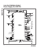
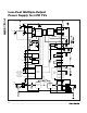
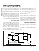
Positive Charge-Pump Regulator
The positive charge-pump regulator is typically used to
generate the positive supply rail for the TFT LCD gate
driver ICs. The output voltage is set with an external
resistive voltage-divider from its output to GND with the
midpoint connected to FBP. The number of charge-
pump stages and the setting of the feedback divider
determine the output voltage of the positive charge-
pump regulator. The charge pump includes a high-side
p-channel MOSFET (P1) and a low-side n-channel
MOSFET (N1) to control the power transfer as shown in
Figure 3.
Low-Cost Multiple-Output
Power Supply for LCD TVs
20 ______________________________________________________________________________________
REF
1.25V
OSC
ERROR
AMPLIFIER
P1
N1
DRVP
C19
C22
D5
C23
C20
C21
GNDP
SUP
FBP
POSITIVE CHARGE-PUMP REGULATOR
INPUT
SUPPLY
OUTPUT
MAX17014
Figure 3. Positive Charge-Pump Regulator Block Diagram