
Datasheet


Maxim Integrated | 23www.maximintegrated.com
MAX16952
36V, 2.2MHz Step-Down Controller
with Low Operating Current
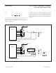
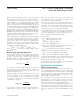
Figure 6. Typical Operating Circuit for V
OUT
= 5V
MAX16952
R8
13kΩ
±1%
R2
10kΩ
D2
BIAS FB
OUT
C2
47μF
50V
FOSC
FSYNC
SGND
R5
7.5kΩ
R1
51.1kΩ
±1%
R3
0.015Ω
±1%
COMP
C9
3300pF
C8
OPEN
C7
2.2μF
C1
0.1μF
C11
4.7μF
50V
C4
0.1μF
SUP
BST
N2
FDS8449
D1
B360B
N1
FDS8449
PGND
DL
L1
1.5μH
LX
V
OUT
5V
6
4
3
PGOOD
10
5
V
L_IN
EN
2
V
EN
1
V
BAT
5.5V TO 36V
CONNECT FSYNC TO BIAS FOR FIXED-FREQUENCY PWM MODE.
CONNECT FSYNC TO SGND FOR SKIP MODE.
THE MAX16952 CAN WORK DOWN TO 3.5V.
713
C6
47μF
6.3V
C5
47μF
6.3V
9
11
12
14
CS
8
16
DH
15
Keep the power traces and load connections short,
especially at the ground terminals. This practice is
essential for high efficiency and jitter-free operation. Use
thick copper PCBs (2oz vs. 1oz) to enhance efficiency.
Place the controller IC adjacent to the synchronous
rectifier MOSFET (NL) and keep the connections for LX,
PGND, DH, and DL short and wide. Use multiple small
vias to route these signals from the top to the bottom
side, if these signals need to be routed in the bottom
layer. The gate current traces must be short and wide,
measuring 50 mils to 100 mils wide if the low-side
MOSFET is 1in from the controller IC. Connect the
PGND trace from the IC close to the source terminal of
the low-side MOSFET.
Route high-speed switching nodes (BST, LX, DH, and
DL) away from the sensitive analog areas (FOSC,
COMP, and FB). Group all SGND-referred and feed-
back components close to the IC. Keep the FB and
compensation network nets as small as possible to pre-
vent noise pickup. Place the sense resistor close to the
IC with short, direct traces, making a Kelvin-sense con-
nection to the current-sense resistor. Place BIAS
capacitor close to the IC and minimize vias in the path
in order to minimize transients on the BIAS line.
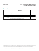
PACKAGE
TYPE
PACKAGE
CODE
OUTLINE
NO.
LAND
PATTERN NO.
16 TSSOP-EP U16E+3
21-0108 90-0120
Package Information
For the latest package outline information and land patterns (foot-
prints), go to www.maximintegrated.com/packages
. Note that a
“+”, “#”, or “-” in the package code indicates RoHS status only.
Package drawings may show a different suffix character, but the
drawing pertains to the package regardless of RoHS status.
Chip Information
PROCESS: BiCMOS