
Datasheet


Maxim Integrated | 21www.maximintegrated.com
MAX16952
36V, 2.2MHz Step-Down Controller
with Low Operating Current
Therefore:
Solving for R
C
:
Set the error-amplifier compensation zero formed by R
C
and C
C
(f
zEA
) at the f
pMOD
. Calculate the value of C
C
as follows:
If f
zMOD
is less than 5 x f
C
, add a second capacitor,
C
F
, from COMP to SGND and set the compensation
pole formed by R
C
and C
F
(f
pEA
) at the f
zMOD
.
Calculate the value of C
F
as follows:
As the load current decreases, the modulator pole also
decreases; however, the modulator gain increases
accordingly and the crossover frequency remains the
same.
For the case where f
zMOD
is less than f
C
:
The power-modulator gain at f
C
is:
The error-amplifier gain at f
C
is:
Therefore:
Solving for R
C
:
Set the error-amplifier compensation zero formed by R
C
and C
C
at the f
pMOD
(f
zEA
= f
pMOD
):
If f
zMOD
is less than 5 × f
C
, add a second capacitor C
F
from COMP to SGND. Set f
pEA
= f
zMOD
and calculate
C
F
as follows:
MOSFET Selection
The MAX16952’s controller drives two external logic-
level n-channel MOSFETs as the circuit switch ele-
ments. The key selection parameters to choose these
MOSFETs include:
• On-resistance (R
DS(ON)
)
• Maximum drain-to-source voltage (V
DS(MAX)
)
• Minimum threshold voltage (V
TH(MIN)
)
• Total gate charge (Q
G
)
• Reverse-transfer capacitance (C
RSS
)
• Power dissipation
C
Rf
F
CzMOD
=
××
1
2π
C
fR
C
MOD C
=
××
1
2
2
π
R
Vf
g V GAIN f
C
OUT C
mEA FB
MOD f
zMOD
C
=
×
×× ×
()
,
GAIN
V
V
gR
f
f
MOD fC
FB
OUT
mEA C
zMOD
C
()
×××× =
,
1
GAIN g R
f
f
EA fC
mEA C
zMOD
C
()
=××
,
GAIN GAIN
f
f
MOD fC MOD dc
pMOD
zMOD
() ()
=×
C
fR
F
zMOD C
=
××
1
2π
C
fR
C
pMOD C
=
××
1
2π
R
V
g V GAIN
C
OUT
mEA FB
MOD fC
=
××
()
,
GAIN
V
V
gR
MOD fC
FB
OUT
mEA C
()
×××=
,
1
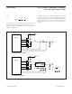
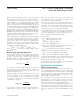
Figure 5. Compensation Network
R1
R
C
R2
C
C
C
F
V
OUT
V
REF
g
m
COMP