
Datasheet


Maxim Integrated | 19www.maximintegrated.com
MAX16952
36V, 2.2MHz Step-Down Controller
with Low Operating Current
Input Capacitor
The input filter capacitor reduces peak currents drawn
from the power source and reduces noise and voltage
ripple on the input caused by the circuit’s switching.
The input capacitor RMS current requirement (I
RMS
) is
defined by the following equation:
I
RMS
has a maximum value when the input voltage
equals twice the output voltage (V
SUP
= 2V
OUT
), so
I
RMS(MAX)
= I
LOAD(MAX)
/2.
Choose an input capacitor that exhibits less than +10°C
self-heating temperature rise at the RMS input current
for optimal long-term reliability.
The input-voltage ripple comprises ΔV
Q
(caused by the
capacitor discharge) and ΔV
ESR
(caused by the ESR of
the capacitor). Use low-ESR ceramic capacitors with
high-ripple current capability at the input. Assume the
contribution from the ESR and capacitor discharge is
equal to 50%. Calculate the input capacitance and ESR
required for a specified input voltage ripple using the
following equations:
where:
and:
where:
Output Capacitor
The output filter capacitor must have low enough ESR
to meet output ripple and load-transient requirements,
yet have high enough ESR to satisfy stability require-
ments. The output capacitance must be high enough to
absorb the inductor energy while transitioning from full-
load to no-load conditions without tripping the overvolt-
age fault protection. When using high-capacitance,
low-ESR capacitors, the filter capacitor’s ESR domi-
nates the output-voltage ripple. The size of the output
capacitor depends on the maximum ESR required to
meet the output-voltage ripple (V
RIPPLE(P-P)
) specifica-
tions:
In skip mode, the inductor current becomes discontinu-
ous, with the peak current set by the skip-mode current-
sense threshold (V
SKIP
= 32mV, typ). In skip mode, the
no-load output ripple can be determined as follows:
The actual capacitance value required relates to the
physical size needed to achieve low ESR, as well as to
the chemistry of the capacitor technology. Thus, the
capacitor is usually selected by ESR and voltage rating
rather than by capacitance value.
When using low-value filter capacitors, such as ceramic
capacitors, size is usually determined by the capacity
needed to prevent V
SAG
and V
SOAR
from causing
problems during load transients. Generally, once
enough capacitance is added to meet the overshoot
requirement, undershoot at the rising load edge is no
longer a problem (see the V
SAG
and V
SOAR
equations
in the
Transient Response
section). However, low-value
filter capacitors typically have high-ESR zeros that can
affect the overall stability.
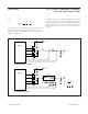
Compensation Design
The MAX16952 uses an internal transconductance error
amplifier with its inverting input and its output available
to the user for external frequency compensation. The
output capacitor and compensation network determine
the loop stability. The inductor and the output capacitor
are chosen based on performance, size, and cost.
Additionally, the compensation network optimizes the
control-loop stability.
The controller uses a current-mode control scheme that
regulates the output voltage by forcing the required
current through the external inductor. The MAX16952
uses the voltage drop across the DC resistance of the
inductor or the alternate series current-sense resistor to
measure the inductor current. Current-mode control
eliminates the double pole in the feedback loop caused
V
V ESR
R
RIPPLE P P
SKIP
SENSE
()−
=
×
V ESR I LIR
RIPPLE P P LOAD MAX() ( )−
=× ×
D
V
V
OUT
SUP
=
C
IDD
Vf
IN
OUT
QSW
=
×−
()
Δ×
1
Δ=
−
()
×
××
I
VV V
VfL
L
SUP OUT OUT
SUP SW
ESR
V
I
I
IN
ESR
OUT
L
=
Δ
+
Δ
2
II
VV V
V
RMS LOAD MAX
OUT SUP OUT
SUP
=
−
()
()