
Datasheet


Maxim Integrated | 17www.maximintegrated.com
MAX16952
36V, 2.2MHz Step-Down Controller
with Low Operating Current
However, if it is necessary, higher inductor values can
be selected.
The exact inductor value is not critical and can be
adjusted to make trade-offs among size, cost, efficien-
cy, and transient response requirements. Table 1
shows a comparison between small and large inductor
sizes.
The minimum practical inductor value is one that
causes the circuit to operate at the edge of critical
conduction (where the inductor current just touches
zero with every cycle at maximum load). Inductor val-
ues lower than this grant no further size-reduction
benefit. The optimum operating point is usually found
between 25% and 45% ripple current. When pulse
skipping (FSYNC low and light loads), the inductor
value also determines the load-current value at which
PFM/PWM switchover occurs.
For the selected inductance value, the actual peak-to-
peak inductor ripple current (ΔI
INDUCTOR
) is defined by:
where ΔI
INDUCTOR
is in mA, L is in μH, and f
SW
is in kHz.
The core must be large enough not to saturate at the
peak inductor current (I
PEAK
):
Transient Response
The inductor ripple current also impacts transient
response performance, especially at low V
SUP
- V
OUT
differentials. Low inductor values allow the inductor cur-
rent to slew faster, replenishing charge removed from
the output filter capacitors by a sudden load step. The
total output voltage sag is the sum of the voltage sag
while the inductor is ramping up and the voltage sag
before the next pulse can occur:
where D
MAX
is the maximum duty factor, L is the induc-
tor value in μH, C
OUT
is the output capacitor value in
μF, t is the switching period (1/f
SW
) in μs, and Δt equals
(V
OUT
/V
SUP
) × t when in fixed-frequency PWM mode, or
L × 0.2 × I
MAX
/(V
SUP
- V
OUT
) when in skip mode. The
amount of overshoot (V
SOAR
) during a full-load to no-
load transient due to stored inductor energy can be cal-
culated as:
Current Sensing
For the most accurate current sensing, use a current-
sense resistor (R
SENSE
) between the inductor and the
output capacitor. Connect CS to the inductor side of
R
SENSE
, and OUT to the capacitor side. Size R
SENSE
such that its maximum current (I
OC
) induces a voltage
of V
LIMIT
(68mV minimum) across R
SENSE
.
If a higher voltage drop across R
SENSE
must be tolerated,
divide the voltage across the sense resistor with a
voltage-divider between CS and OUT to reach V
LIMIT
(68mV minimum).
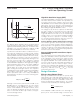
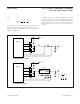
The current-sense method (Figure 4) and magnitude
determine the achievable current-limit accuracy and
power loss. Typically, higher current-sense limits
provide tighter accuracy, but also dissipate more
power. For the best current-sense accuracy and over-
current protection, use a ±1% tolerance current-sense
resistor with low parasitic inductance between the
inductor and output as shown in Figure 4a.
Alternatively, high-power applications that do not
require highly accurate current-limit protection can
reduce the overall power dissipation by connecting a
series RC circuit across the inductor (Figure 4b) with an
equivalent time constant:
R
R
RR
R
CSHL DCR
=
+
⎛
⎝
⎜
⎞
⎠
⎟
2
12
V
IL
CV
SOAR
LOAD MAX
OUT OUT
≈
Δ
()
()
2
2
V
LI
CVD V
SAG
LOAD MAX
OUT SUP MAX OUT
=
Δ
()
×
()
−
()
()
2
2
++
Δ−Δ
()
Itt
C
LOAD MAX
OUT
()
II
I
PEAK LOAD MAX
INDUCTOR
=+
Δ
()
2
Δ=
−
()
××
I
VV V
VfL
INDUCTOR
OUT SUP OUT
SUP SW
INDUCTOR SIZE
SMALLER LARGER
Lower price Smaller ripple
Smaller form factor Higher efficiency
Faster load response
Larger fixed-frequency range
in skip mode
Table 1. Inductor Size Comparison