
Datasheet


MAX16952
Maxim Integrated | 16www.maximintegrated.com
36V, 2.2MHz Step-Down Controller
with Low Operating Current
not meet the above condition, then pulse skipping
occurs to decrease the effective duty cycle. To avoid
this, decrease the switching frequency or lower the
input voltage (V
SUP
).
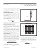
Setting the Output Voltage
Connect FB to BIAS to enable the fixed step-down con-
troller output voltage (5V), set by a preset, internal
resistive voltage-divider connected between the output
(OUT) and SGND.
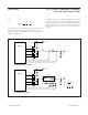
To achieve other output voltages between 1V to 10V,
connect a resistive divider from OUT to FB to SGND
(Figure 2). Select R
FB2
(FB to SGND resistor) less than
or equal to 100kΩ. Calculate R
FB1
(OUT to FB resistor)
with the following equation:
where V
FB
= 1V (typ) (see the
Electrical Characteristics
table) and V
OUT
can range from 1V to 10V.
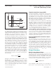
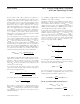
Setting the Switching Frequency
The switching frequency, f
SW
, is set by a resistor
(R
FOSC
) connected from FOSC to SGND. See Figure 3
to select the correct R
FOSC
value for the desired
switching frequency.
For example, a 2MHz switching frequency is set with
R
FOSC
= 14.3kΩ. Higher frequencies allow designs with
lower inductor values and less output capacitance.
Consequently, peak currents and I
2
R losses are lower
at higher switching frequencies, but core losses, gate-
charge currents, and switching losses increase.
Inductor Selection
Three key inductor parameters must be specified for
operation with the MAX16952: inductance value (L),
inductor saturation current (I
SAT
), and DC resistance
(R
DCR
). To select inductance value, the ratio of inductor
peak-to-peak AC current to DC average current (LIR)
must be selected first. A good compromise between
size and loss is a 30% peak-to-peak ripple current to
average-current ratio (LIR = 0.3). The switching fre-
quency, input voltage, output voltage, and selected LIR
then determine the inductor value as follows:
where V
SUP(MIN)
is the minimum supply voltage, V
OUT
is
the typical output voltage, and I
OUT(MAX)
is the maximum
load current. The switching frequency is set by R
FOSC
(see the
Setting the Switching Frequency
section).
The MAX16952 uses internal frequency independent
slope compensation to ensure stable operation at duty
cycles above 50%. Use the equation below to select
the inductor value:
VV
LH f MHz
OUT
SW
[]
[] [ ]
%
μ×
=±125
L
VV V
VfI
OUT SUP MIN OUT
SUP MIN SW OUT MA
=
−
()
××
()
() (
XX
LIR
)
×
RR
V
V
FB FB
OUT
FB
12
1=
⎛
⎝
⎜
⎞
⎠
⎟
−
⎡
⎣
⎢
⎢
⎤
⎦
⎥
⎥
Figure 2. Adjustable Output Voltage
MAX16952
R
FB2
R
FB1
OUT
FB
Figure 3. Switching Frequency vs. R
FOSC
SWITCHING FREQUENCY vs. R
FOSC
MAX16952 toc07
R
FOSC
(kI)
SWITHCING FREQUENCY (MHz)
3530252015
1.2
1.4
1.6
1.8
2.0
2.2
2.4
2.6
2.8
3.0
1.0
10 40