
Datasheet


Maxim Integrated | 13www.maximintegrated.com
MAX16952
36V, 2.2MHz Step-Down Controller
with Low Operating Current
Error Detection and Fault Behavior
Several error-detection mechanisms prevent damage to
the MAX16952 and the application circuit:
• Overcurrent protection
• Output overvoltage protection
• Undervoltage lockout at BIAS
• Power-good detection of the output voltage
• Overtemperature protection of the IC
Overcurrent Protection
The MAX16952 provides cycle-by-cycle current limiting
as long as the FB voltage is greater than 0.7V (i.e., 70%
of the regulated output voltage). If the output voltage
drops below 70% of the regulation point due to overcur-
rent event, 16 consecutive current-limit events initiate
restart. If the overcurrent is still present during restart,
the MAX16952 shuts down and initiates restart. This
automatic restart continues until the overcurrent condi-
tion disappears. If the overcurrent condition disappears
at any restart attempt, the device enters the normal
soft-start routine.
Output Overvoltage Protection
The MAX16952 features an internal output overvoltage
protection. If V
OUT
increases by 13% (typ) of the
intended regulation voltage, the high-side MOSFET
turns off and the low-side MOSFET turns on. The low-
side MOSFET stays on until V
OUT
goes back into regu-
lation. Once V
OUT
is in regulation, the normal switching
cycles continue.
Undervoltage Lockout (UVLO)
The BIAS input undervoltage lockout (UVLO) circuitry
inhibits switching if the 5V bias supply (BIAS) is below
its UVLO threshold, 3.1V (typ). If the BIAS voltage
drops below the UVLO threshold, the controller stops
switching and turns off both high-side and low-side
gate drivers until the BIAS voltage recovers.
Power-Good Detection (PGOOD)
The MAX16952 includes a power-good comparator with
added hysteresis to monitor the step-down controller’s
output voltage and detect the power-good threshold. The
PGOOD output is open drain and should be pulled up
with an external resistor to the supply voltage of the logic
input it drives. This voltage should not exceed 6V. Pullup
resistor should not be less than 1kΩ , such that pulldown
voltage is less than 400mV with a 5V supply. PGOOD can
sink up to 3mA of current while low.
PGOOD asserts low during the following conditions:
• Standby mode
• Undervoltage with V
OUT
below 88% (typ) its set
value
• Overvoltage with V
OUT
above 113% (typ) its set
value
The power-good levels are measured at FB if a feed-
back divider is used. If the MAX16952 is used in 5V
mode with FB connected to BIAS, OUT is used as a
feedback path for voltage regulation and power-good
determination.
Overtemperature Protection
Thermal-overload protection limits total power dissipa-
tion in the MAX16952. When the junction temperature
exceeds +175°C (typ), an internal thermal sensor shuts
down the step-down controller, allowing the IC to cool.
The thermal sensor turns on the IC again after the junc-
tion temperature cools by 15°C and the output voltage
has dropped below 1.25V (typ).
A continuous overtemperature condition can cause
on-/off-cycling of the device.
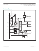
Fixed-Frequency, Current-Mode
PWM Controller
The MAX16952’s step-down controller uses a PWM,
current-mode control scheme. An internal transconduc-
tance amplifier establishes an integrated error voltage.
The heart of the PWM controller is an open-loop com-
parator that compares the integrated voltage-feedback
signal against the amplified current-sense signal plus
the slope compensation ramp, which are summed into
the main PWM comparator to preserve inner-loop sta-
bility and eliminate inductor stair-casing. At each falling
edge of the internal clock, the high-side MOSFET turns
on until the PWM comparator trips, the maximum duty
cycle is reached, or the peak current limit is reached.
During this on-time, current ramps up through the
inductor, storing energy in its magnetic field and sourc-
ing current to the output. The current-mode feedback
system regulates the peak inductor current as a func-
tion of the output-voltage error signal. The circuit acts
as a switch-mode transconductance amplifier and elim-
inates the influence of the output LC filter double pole.
During the second half of the cycle, the high-side
MOSFET turns off and the low-side MOSFET turns on.
The inductor releases the stored energy as the current
ramps down, providing current to the output. The out-
put capacitor stores charge when the inductor current