
Datasheet

MAX16952
Maxim Integrated | 10www.maximintegrated.com
36V, 2.2MHz Step-Down Controller
with Low Operating Current
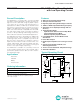
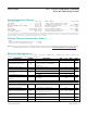
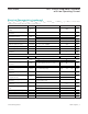
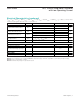
Pin Description (continued)
PIN NAME FUNCTION
9 OUT
Output Sense and Negative Current-Sense Input. When using the internal preset 5V feedback divider
(FB = BIAS), the controller uses OUT to sense the output voltage. Connect OUT to the negative terminal of
the current-sense element.
10 PGOOD
Open-Drain Power-Good Output. A logic-high voltage on PGOOD indicates that the output voltage is in
regulation. PGOOD is pulled low when the output voltage is out of regulation. Connect a 10k_ pullup
resistor from PGOOD to the digital interface voltage.
11 PGND
Power Ground. Connect the input and output filter capacitors’ negative terminals to PGND. Connect PGND
externally to SGND at a single point.
12 DL
Low - S i d e G ate- D r i ver O utp ut. D L sw i ng s fr om V
B IA S
to P GN D . If a r esi stor i s need ed b etw een D L and the g ate
of the M OS FE T, the p r op er r esi stance val ue coul d b e p r ovi d ed b ased on ap p l i cati on ci r cui t r evi ew r esul t.
13 BIAS
Internal 5V Linear Regulator Output. BIAS provides power for bias and gate drive. Connect a 2.2μF to 10μF
ceramic capacitor from BIAS to PGND.
14 LX
External Inductor Connection. Connect LX to the switched side of the inductor. LX serves as the lower
supply rail for the DH high-side gate driver.
15 DH
High-Side Gate-Driver Output. DH swings from LX to BST. If a r esi stor i s need ed b etw een D H and the g ate of
the M OS FE T, the p r op er r esi stance val ue coul d b e p r ovi d ed b ased on ap p l i cati on ci r cui t r evi ew r esul t.
16 BST
Boost Flying Capacitor Connection. Connect a ceramic capacitor between BST and LX. See the Boost-
Flying Capacitor Selection section for details.
—EP
Exposed Pad. Internally connected to ground. Connect EP to a large contiguous copper plane at SGND
potential to improve thermal dissipation. Do not use as the main ground connection.