
Datasheet

MOSFET Selection
The MAX16819/MAX16820’s gate driver is capable of
sourcing 0.5A and sinking 1A of current. MOSFET
selection is based on the maximum input operating
voltage V
IN
, output current I
LED
, and operating switch-
ing frequency. Choose a MOSFET that has a higher
breakdown voltage than the maximum operation voltage,
low R
DS(ON)
, and low total charge for better efficiency.
MOSFET threshold voltage must be adequate if operated
at the low end of the input-voltage operating range.
Freewheeling Diode Selection
The forward voltage of the freewheeling diode should be
as low as possible for better efficiency. A Schottky diode
is a good choice as long as the breakdown voltage is high
enough to withstand the maximum operating voltage.
The forward current rating of the diode must be at least
equal to the maximum LED current.
LED Current Ripple
The LED current ripple is equal to the inductor current
ripple. In cases when a lower LED current ripple is need-
ed, a capacitor can be placed across the LED terminals.
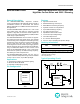
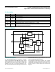
PCB Layout Guidelines
Careful PCB layout is critical to achieve low switching
losses and stable operation. Use a multilayer board when-
ever possible for better noise immunity. Minimize ground
noise by connecting high-current ground returns, the input
bypass-capacitor ground lead, and the output-filter ground
lead to a single point (star ground configuration). In normal
operation, there are two power loops. One is formed when
the MOSFET is on and the high current flows through IN—
R
SENSE
—LEDs—Inductor—MOSFET—GND. The other
loop is formed when the MOSFET is off when the high
current circulates through R
SENSE
—LEDs—Inductor—
freewheeling diode. To minimize noise interaction, each
loop area should be as small as possible.
Place R
SENSE
as close as possible to the input filter
and IN. For better noise immunity, a Kelvin connection
is strongly recommended between CSN and R
SENSE
.
Connect the exposed paddle to a large-area ground plane
for improved power dissipation.
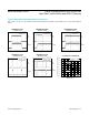
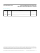
PACKAGE
TYPE
PACKAGE
CODE
OUTLINE
NO.
LAND
PATTERN NO.
6 TDFN-EP T633+2 21-0137 90-0058
MAX16819/MAX16820 2MHz High-Brightness LED Drivers with
High-Side Current Sense and 5000:1 Dimming
www.maximintegrated.com
Maxim Integrated
│
8
Chip Information
PROCESS: BiCMOS
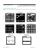
Package Information
For the latest package outline information and land patterns
(footprints), go to www.maximintegrated.com/packages. Note
that a “+”, “#”, or “-” in the package code indicates RoHS status
only. Package drawings may show a different suffix character, but
the drawing pertains to the package regardless of RoHS status.