
Datasheet


Multiplexer and A/D Conguration
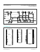
A conversion is started with a WR pulse. All channels
sample on WR’s falling edge. Mux configuration data is
loaded on WR’s rising edge. In I/O mode (MODE = Open
Circuit), selections for channel number, single or multi-
channel conversion, unipolar or bipolar input, and single-
ended or differential input are made with A0-A2, ALL, BIP,
and DIFF (Table 1). These input pins are also shared with
the RAM data outputs D0–D7. An alternate, simpler inter-
face is provided by the hard-wired mode, which selects
some general mux configurations without requiring ADC
programming. Hard-wired connections of MODE and V
SS
select from 4 mux configurations as listed in Tab le 4 (see
the
Hard-Wired Mode section).
On the rising edge of WR, the mux configuration register
is updated; falling edge initiates sampling of all inputs.
A channel selection can be implemented on the current
conversion, but changes from unipolar to bipolar (with
BIP) or from single ended to differential operation (with
DIFF) do not go into effect until the following WR. This can
be overcome by writing to the configuration register while
inhibiting the conversion (INH = 1), or by changing DIFF
and BIP one conversion early, i.e. on the previous write.
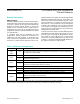
Table 2. Single-Ended Channel Selection (MODE = Open Circuit)
Table 3. Differential Channel Selection (MODE = Open Circuit)
Note: Shaded areas represent MAX156 operation.
Note: Shaded areas represent MAX156 operation.
MUX ADDRESS SINGLE-ENDED CHANNEL SELECTION
A0 A1 A2 DIFF 0 1 2 3 4 5 6 7 AGND
0 0 0 0 + -
1 0 0 0 + -
0 1 0 0 + -
1 1 0 0 + -
0 0 1 0 + -
1 0 1 0 + -
0 1 1 0 + -
1 1 1 0 + -
MUX ADDRESS DIFFERENTIAL CHANNEL SELECTION
A0 A1 A2 DIFF 0 1 2 3 4 5 6 7
0 0 0 1 + -
0 1 0 1 + -
0 0 1 1 + -
0 1 1 1 + -
1 0 0 1 - +
1 1 0 1 - +
1 0 1 1 - +
1 1 1 1 - +
MAX155/MAX156 8-/4-Channel ADCs with Simultaneous
T/Hs and Reference
www.maximintegrated.com
Maxim Integrated
│
9