
Datasheet


V
DD
to AGND ............................................................. -0.3V, +6V
V
DD
to DGND ............................................................. -0.3V, +6V
AGND to DGND ...........................................-0.3V, (V
DD
+ 0.3V)
V
SS
to AGND.............................................................. +0.3V, -6V
V
SS
to DGND ............................................................. +0.3V, -6V
CS, WR, RD, CLK, MODE to DGND ...........-0.3V, (V
DD
+ 0 3V)
BUSY, D0–D7 to DGND ...............................-0.3V, (V
DD
+ 0 3V)
REFOUT to AGND .......................................-0.3V, (V
DD
+ 0 3V)
REFIN to AGND ...........................................-0.3V, (V
DD
+ 0 3V)
AIN to AGND .................................... (V
SS
- 0.3V), (V
DD
+ 0 3V)
Output Current (REFOUT) .................................................30mA
Continuous Power Dissipation (T
A
= +70°C)
24-Pin PDIP (derate 8.7mW/°C above +70°C) ............696mW
28-Pin PDIP (derate 9.09mW/°C above +70°C) ..........727mW
28-Pin Wide SO (derate 12.5mW/°C above +70°C) ..1000mW
Operating Temperature Ranges:
MAX155/MAX156_C_ _ ......................................0°C to +70°C
MAX155/MAX156_E_ _ .................................. -40°C to +85°C
Storage Temperature Range ............................ -65°C to +150°C
Lead Temperature (soldering, 10s) .................................+300°C
Soldering Temperature (reflow) .......................................+260°C
(V
DD
= +5V, V
REFIN
= +2.5V. External Reference, V
AGND
= V
DGND
= 0V, V
SS
= 0V or -5V, f
CLK
= 5MHz external, Unipolar range
single-ended mode, T
A
= T
MIN
to T
MAX
, unless otherwise noted.)
PARAMETER SYMBOL CONDITIONS MIN TYP MAX UNITS
ACCURACY (Note 1)
Resolution 8 Bits
Integral Linearity Error
MAX15_A ±½
LSB
MAX15_B ±1
No Missing Codes Resolution Guaranteed monotonic 8 Bits
Offset Error (Unipolar)
MAX15_A ±½
LSB
MAX15_B ±1
Offset Error (Bipolar)
MAX15_A ±1
LSB
MAX15_B ±2
Gain Error
Unipolar
MAX15_A ±1
LSB
MAX15_B ±1
Bipolar
MAX15_A ±1
MAX15_B ±2
Channel-to-Channel Matching
MAX15_A ±½
LSB
MAX15_B ±1
DYNAMIC PERFORMANCE (V
IN
= 50kHz, 2.5V
P-P
sine wave sampled at 220ksps)
Signal-to-Noise and Distortion
Ratio
SINAD
MAX15_A 48
dB
MAX15_B 47
Total Harmonic Distortion THD -60 dB
Spurious-Free Dynamic Range SFDR -62 dB
Small-Signal Bandwidth 4 MHz
Aperture Delay 20 ns
Aperture Delay Matching (Note 2) 4 ns
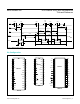
MAX155/MAX156 8-/4-Channel ADCs with Simultaneous
T/Hs and Reference
www.maximintegrated.com
Maxim Integrated
│
2
Absolute Maximum Ratings
Stresses beyond those listed under “Absolute Maximum Ratings” may cause permanent damage to the device. These are stress ratings only, and functional operation of the device at these
or any other conditions beyond those indicated in the operational sections of the specifications is not implied. Exposure to absolute maximum rating conditions for extended periods may affect
device reliability.
Electrical Characteristics