
Datasheet


Hard-Wired Mode
For simpler applications, the MODE and V
SS
pins can be
hard-wired to specify the type of conversion as outlined
in Table 4. In this mode, the configuration register is not
used, so input data on DO-D7 is ignored. For example,
with MODE tied low, an 8-channel, single-ended conver
sion begins with WR With MODE tied high, a 4-channel,
differential conversion is init iated with WR. Again, the
configuration register is not affected by the data present
on 00-07. These conversions are otherwise identical to
those shown in Figure 4.
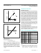
Analog Considerations
lntemal Reference
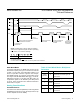
The internal 2.5V reference (REFOUT) must be bypassed
to AGND (Figure 8a) with a 4.7µF electrolytic and a 0.1µF
ceramic capacitor to ensure stability.
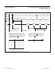
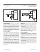
Figure 6. Input/Output Mode Timing–Reading Arbitrary RAM Locations
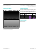
Table 4. Hard-Wired Mode—Multiplexer
Selections
MODE V
SS
CONVERSION TYPE
OPEN
CIRCUIT
X
Multiplexer conguration register
determines conversion type. Not
hard-wired.
0 AGND
8-Channel, Single-Ended, Unipolar
Conversion
1 AGND
4-Channel, Differential, Unipolar
Conversion
0 -5V
8-Channel, Single-Ended, Bipolar
Conversion
1 -5V
4-Channel, Differential, Bipolar
Conversion
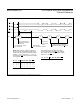
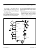
INH = 0
DATA IN
DATA OUT DATA OUT
INH = 1
DATA OUT
INH = 0
DATA IN
UPDATE CONFIGURATION REGISTER
AND BEGIN NEW CONVERSION
END OF
CONVERSION
READ DATA INDICATED
BY ADDRESS
UPDATE CONFIGURATION
REGISTER WITH NEW
ADDRESS
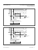
READ DATA
AT ADDRESS
UPDATE
CONFIGURATION
REGISTER BEGIN
CONVERSION
ALL CHANNELS ARE
SAMPLED HERE
NOTE: A RAM location is read by writing the following
data into the configuration register and when performing
a RD. If INH = 0, a conversion will begin.
S = May be selected
X = Don’t Care for this WR if INH = 0, but may effect next conversion.
A0 A1 A2 PD INH BIP DIFF ALL
S S S 0 1 X X 1
t
CONV
CS
WR
RD
BUSY
D0-D7
MAX155/MAX156 8-/4-Channel ADCs with Simultaneous
T/Hs and Reference
www.maximintegrated.com
Maxim Integrated
│
14