
Instruction Manual

MAX15303 PMBus Command Set User’s Guide
Page 50 of 52
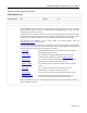
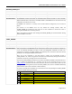
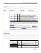
DEADTIME_GCTRL
7
TDF (MSB)
Integer
(AGD system disabled, do not alter this value)
8 LXDAC
Unsigned
Byte
(AGD system disabled, do not alter this value) 15
9
GCTRL[0]
Unsigned
Byte
Function disabled; not applicable 0
10
GCTRL[1]
Unsigned
Byte
Function disabled; not applicable 0
11
GCTRL[2]
Unsigned
Byte
Function disabled; not applicable 0
12
GCTRL[3]
Unsigned
Byte
Function disabled; not applicable 0
13
GCTRL[4]
Unsigned
Byte
Function disabled; not applicable 0
14
GCTRL[5]
Unsigned
Byte
Function disabled; not applicable 0
15
GCTRL[6]
Unsigned
Byte
Function disabled; not applicable 0
16
GCTRL[7]
Unsigned
Byte
Function disabled; not applicable 0
17
GCTRLDAC (LSB)
Unsigned
Integer
Function disabled; not applicable 0
18
GCTRLDAC (MSB)
Non-overlap/Deadtime Adjustment
The fixedDTR and fixedDTF terms adjust the gate-drive non-overlap timing. For the MAX15303, these
deadtime adjustment values are in nanoseconds, and constant timing is maintained regardless of
switching frequency.
Caution must be exercised when trimming the gate-drive non-overlap timing; it is possible to set
negative values and cause the high-side driver to enable before the low-side driver has disabled, and
vice-versa.
Body-Diode Conduction Comparator
The LXDAC term is used to adjust the low-side MOSFET body-diode conduction detection comparator
reference threshold. Note: the default setting is LXDAC = 15 and this value should not be changed.
Gate-Drive Voltage
Unlike some other Maxim digital power controllers, the MAX15303 does not allow adjustment of the
gate drive voltage because of the use of internal MOSFETs which are optimized for operation at a fixed
drive voltage.
Wait at least 500ms for execution after sending the DEADTIME_GCTRL command before sending
additional PMBus commands.
ZETA_P
Reference:
Maxim Specific
Lockable:
Yes
Command Code:
0xE8
Format:
Linear