
Instruction Manual

MAX15303 PMBus Command Set User’s Guide
Page 15 of 52
INTERLEAVE
ADDR1 pins, unless a new value of INTERLEAVE has been written to the User Store. The value of the
ADDR0 and ADDR1 pin resistance is measured only once during initialization (power-up).
Because the MAX15303 uses one of two different PWM “speed modes” depending on the switching
frequency selected (see FREQUENCY_SWITCH
), the INTERLEAVE command will show unexpected
results if switching frequency crosses the 475kHz speed-mode boundary after initialization.
The MAX15303 includes enhancements beyond the PMBus specification INTERLE
AVE command
functionality:
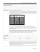
• Setting the “Number In Group” to zero will be interpreted by the MAX15303 as 16 possible
phases. This allows phase-spreading in 22.5º increments.
• The low nibble of the high byte of INTERLEAVE contains the “Group ID Number” per the
PMBus specification, but this is a value that has no function and no dependent parameters in
either the MAX15303 device or in the PMBus specification. As a result, it is not necessary to
set a “Group ID Number.” Both n
ibbles of the high byte of INTERLEAVE can be used
separately or together as “scratchpad” data, if desired.