
Instruction Manual


MAX15303 PMBus Command Set User’s Guide
Page 12 of 52
VOUT_TRANSITION_RATE
Reference:
Standard Command
Lockable:
Yes
Command Code:
0x27
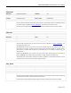
Format:
Linear
Data Bytes:
2
Units:
mV/μs (or V/ms, kV/s)
Transfer:
Read/Write Word
Factory Value:
0x9B33 (0.1V/ms, see Description)
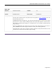
Description/Notes:
See Section 13.8 of the PMBus Specification Part II.
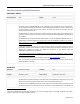
To achieve output voltage slew-rate control, the MAX15303 has an 8-bit timer with approximately
243ns resolution. When the timer expires, the 12-bit voltage setpoint is incremented or decremented
until the setpoint reaches its final value. This limits the minimum and maximum possible slew-rates
for each feedback divider range as follows:
Feedback
VOUT_TRANSITION_RATE, kV/s
Divider
Min
Max
0
≈ 0.005
≈ 1.171
1
≈ 0.005
≈ 1.323
2
≈ 0.006
≈ 1.519
3
≈ 0.007
≈ 1.782
4
≈ 0.008
≈ 2.16
5
≈ 0.011
≈ 2.736
6
≈ 0.015
≈ 3.725
7
≈ 0.023
≈ 5.862
For each divider range, the minimum transition rate is also the resolution (minimum step size).
The desired value of VOUT_TRANSITION_RATE is retained in memory, regardless of hardware
limitations imposed by the feedback divider range, but the read-back value is
based on actual
hardware register settings.
If a commanded value of VOUT_TRANSITION_RATE exceeds the maximum possible slew-rate for the
feedback divider range, the MAX15303 sets the slew-rate control timer to zero, and the output
voltage setpoint is updated to the new setpoint value immediately and without delay. In this case,
VOUT_TRANSITION_RATE will read back as 0mV/μs to avoid a divide-by-zero operation.
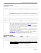
VOUT_DROOP
Reference:
Standard Command
Lockable:
Yes
Command Code:
0x28
Format:
Linear
Data Bytes:
2
Units:
mΩ (or mV/A)
Transfer:
Read/Write Word
Factory Value:
0x0000 (0mΩ)
Description/Notes:
See Section 13.9 of the PMBus Specification Part II.
The MAX15303 uses low-pass filtered inductor DCR current-sense information (i.e., the READ_IOUT
signal) to establish the load-line characteristic according to the VOUT_DROOP value. Because of this
low-pass filtering of the load current information, there will be some settling time in the output
voltage positioning when VOUT_DROOP is non-zero.
It is also important to calibrate READ_IOUT using IOUT_CAL_GAIN and IOUT_CAL_OFFSET to achieve