
Manual

MAX15301 PMBus Command Set User’s Guide
Rev 1 Page 52 of 53
DEADTIME_GCTRL
255
-1200
Note: the default setting is LXDAC = 15 and this value should not be changed.
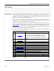
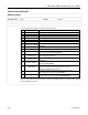
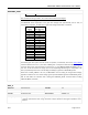
Variable Gate-Drive Voltage
The MAX15301 allows adjustment of the gate drive voltage from approximately 5.2V to 8.7V, as
controlled by a 4-bit DAC. The DAC value to gate-drive voltage relationship is as follows:
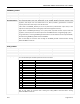
GCTRLDAC
Setting
Typical
Gate Drive (V)
0
5.2
1
5.4
2
5.7
3
5.9
4
6.1
5
6.4
6
6.6
7
6.8
8
7.1
9
7.3
10
7.5
11
7.8
12
8
13
8.2
14
8.5
15
8.7
The variable gate drive system has two modes of operation, controlled by bit 6 of the LOOP_CONFIG
command. When bit 6 is set to 1, the value of READ_IOUT is compared to determine which of “eighth”
of the full load current range the device is operating in; e.g. 0 to IMAX/8, IMAX/8 to IMAX/4, etc. For
each “bin” of the full load current range, there is a corresponding DAC setting in a lookup table. This
table is populated by values sent in the GCTRL[0] to GCTRL[7] arguments of DEADTIME_GCTRL.
When bit 6 of LOOP_CONFIG is set to 0, the MAX15301 uses one setting for the gate-drive voltage,
regardless of load current. This “fixed” setting is given by the GCTRLDAC argument of DEADTIME_GCTRL.
Wait at least 500ms for execution after sending the DEADTIME_GCTRL command before sending
additional PMBus commands.
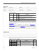
ZETA_P
Reference:
Maxim Specific
Lockable:
Yes
Command Code:
0xE8
Format:
Linear
Data Bytes:
2
Units:
Scalar
Transfer:
Read/Write Byte
Factory Value:
0xBB00 (1.5)
Description/Notes:
The ZETA_P command sets the damping ratio for the closed-loop response. The value can be changed
to improve performance when using nonceramic output capacitors with higher equivalent series
resistance.