
Manual

MAX15301 PMBus Command Set User’s Guide
Rev 1 Page 51 of 53
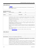
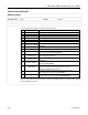
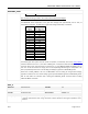
DEADTIME_GCTRL
6
TDF (LSB)
Signed
Integer
AGD system falling edge deadtime target value 8
7
TDF (MSB)
8 LXDAC
Unsigned
Byte
AGD system body-diode conduction comparator
threshold DAC setting
15
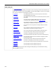
9 GCTRL[0]
Unsigned
Byte
Variable gate drive voltage DAC lookup table
value, bin 0
0
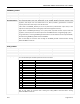
10 GCTRL[1]
Unsigned
Byte
Variable gate drive voltage DAC lookup table
value, bin 1
0
11 GCTRL[2]
Unsigned
Byte
Variable gate drive voltage DAC lookup table
value, bin 2
5
12 GCTRL[3]
Unsigned
Byte
Variable gate drive voltage DAC lookup table
value, bin 3
5
13 GCTRL[4]
Unsigned
Byte
Variable gate drive voltage DAC lookup table
value, bin 4
8
14 GCTRL[5]
Unsigned
Byte
Variable gate drive voltage DAC lookup table
value, bin 5
10
15 GCTRL[6]
Unsigned
Byte
Variable gate drive voltage DAC lookup table
value, bin 6
12
16 GCTRL[7]
Unsigned
Byte
Variable gate drive voltage DAC lookup table
value, bin 7
15
17
GCTRLDAC (LSB)
Unsigned
Integer
Constant gate drive voltage DAC value 0
18
GCTRLDAC (MSB)
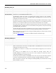
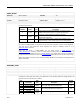
Nonoverlap/Deadtime Adjustment
There are two sets of deadtime adjustment values: the fixedDTR and fixedDTF terms adjust the
nonoverlap
timing when the AGD system is disabled, whereas the TDR and TDF values provide
corresponding target values that are used when the AGD system is enabled.
Note that the AGD system is disabled by default (bit 4 of the LOOP_CONFIG command) and operation of
the AGD system is not recommended or supported by Maxim.
The deadtime adjustment values are given in “vernier tick” units, such that each step results in a
deadtime adjustment as follows:
FREQUENCY_SWITCH ≤ 475kHz: 1 vernier tick = 1 / (FREQUENCY_SWITCH * 2048)
FREQUENCY_SWITCH > 475kHz: 1 vernier tick = 1 / (FREQUENCY_SWITCH * 1024)
Caution must be exercised when trimming the gate-drive nonoverlap timing; it is possible to set negative
values and cause the high-side driver to enable before the low-side driver has disabled, and vice-versa.
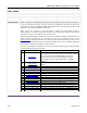
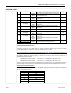
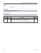
Body-Diode Conduction Comparator
The LXDAC term is used to adjust the low-side MOSFET body-diode conduction detection comparator
reference threshold as follows:
LXDAC Setting
Comparator Threshold (mV)
1
-150
3
-300
7
-450
15
-600
31
-750
61
-900
127
-1000