
Manual

MAX15301 PMBus Command Set User’s Guide
Rev 1 Page 50 of 53
COMP_MODEL
Reference:
Maxim Specific
Lockable:
Yes
Command Code:
0xDB
Format:
Linear
Data Bytes:
6 (see Description)
Units:
Scalar
Transfer:
Read/Write Block
Factory Value:
0.03167, 0.5, 0.5
Description/Notes:
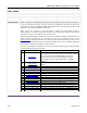
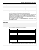
The COMP_MODEL command provides access to key control loop tuning parameters. The three
arguments are as follows:
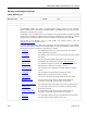
Data Byte
Number
Data Byte
Name Units Description
0 F
LC
/F
SW
None
Power stage LC double-pole frequency, as a fraction of the
PWM fundamental frequency. In typical operation, this
parameter is determined by parametric extraction.
1 F
Z
/F
SW
None
Output capacitor ESR zero frequency, as a fraction of the PWM
fundamental frequency.
2 Z
LC
None
Power stage damping factor. Higher values indicate a more
damped LC filter; lower values represent a less damped filter.
The values of COMP_MODEL can be altered by the parametric extraction function of the MAX15301.
The
y will reset to the USER store values whenever the output is disabled, unless bit 3 of
ADAPTIVE_MODE is cleared.
Note that the values in COMP_MODEL are not saved during a STORE_USER_ALL or
STORE_DEFAULT_ALL
operation, unless the values have previously been set by a PMBus write to
COMP_MODEL, as indicated by bit 14 of STRAP_DISABLE.
This safety feature prevents inadvertent
storage of parametric extraction results that could adversely affect the initial ramp control loop tuning.
Wait at least 500μs for execution after sending the COMP_MODEL command before sending additional
PMBus commands.
DEADTIME_GCTRL
Reference:
Maxim Specific
Lockable:
Yes
Command Code:
0xE7
Format:
See Description
Data Bytes:
19
Units:
N/A
Transfer:
Read/Write Block
Factory Value:
See Description
Description/Notes:
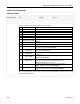
The DEADTIME_GCTRL command allows configuration of the Adaptive Gate-Drive timing system (AGD),
adjustment of static gate-drive timing, and adjustment of the variable gate-drive voltage system. The
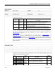
arguments for this command are as follows:
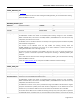
Byte
# Data Name
Data
Type Description
Default
Value
0
fixedDTR (LSB)
Signed
Integer
Static rising-edge deadtime adjustment 20
1
fixedDTR (MSB)
2
fixedDTF (LSB)
Signed
Integer
Static falling-edge deadtime adjustment 20
3
fixedDTF (MSB)
4
TDR (LSB)
Signed
Integer
AGD system rising edge deadtime target value 3
5
TDR (MSB)