
Datasheet


High-Efficiency, 3A, Current-Mode
Synchronous, Step-Down Switching Regulator
MAX15058
18 _____________________________________________________________________________________
( )
( )
LOAD S
SW
C CO OUT
MV MC LOAD
S
LOAD SW
R K 1 D 0.5
1
L f
R1 R2
R 2 f C
R2 g g R
1
ESR
K 1 D 0.5
1
R L f
− −
+
×
+
= × × π ×
× ×
+
− −
+
×
and where the ESR is much smaller than the parallel
combination of the equivalent load resistance and the
current loop impedance, e.g.,:
( )
S
LOAD SW
1
ESR
K 1 D 0.5
1
R L f
<<
− −
+
×
R
C
becomes:
CO OUT
C
MV MC
2 f C
R1 R2
R
R2 g g
π ×
+
= ×
×
3) Determine C
C
by selecting the desired first sys-
tem zero, f
Z1
, based on the desired phase margin.
Typically, setting f
Z1
below 1/5 of f
CO
provides suf-
ficient phase margin.
CO
Z1
C C
f
1
f
2 C R 5
= ≤
π ×
therefore:
C
CO C
5
C
2 f R
≥
π × ×
4) For low duty-cycle applications, the addition of a
phase-leading capacitor (C
FF
in Figure 1) helps
mitigate the phase lag of the damped half-frequency
double pole. Adding a second zero near to but below
the desired crossover frequency increases both the
closed-loop phase margin and the regulator’s unity-
gain bandwidth (crossover frequency). Select the
capacitor as follows:
( )
FF
CO
1
C
2 f R1|| R2
=
π × ×
This guarantees the additional phase-leading zero
occurs at a frequency lower than f
CO
from:
PHASE_LEAD
FF
1
f
2 C R1
=
π × ×
Using C
FF
the zero-pole order is adjusted as follows:
P1 P2 Z1
FF FF
CO P3 Z2
1 1
f f f
2 C R1 2 C (R1||R2)
f f f
< ≤ < < ≈
π π
< <
Confirm the desired operation of C
FF
empirically. The
phase lead of C
FF
diminishes as the output voltage
is a smaller multiple of the reference voltage, e.g.,
below about 1V. Do not use C
FF
when V
OUT
= V
FB
.
Setting the Soft-Start Time
The soft-start feature ramps up the output voltage slowly,
reducing input inrush current during startup. Size the
C
SS
capacitor to achieve the desired soft-start time, t
SS,
using:
SS SS
SS
FB
I t
C
V
×
=
I
SS
, the soft-start current, is 10FA (typ) and V
FB
, the
output feedback voltage threshold, is 0.6V (typ). When
using large C
OUT
capacitance values, the high-side
current limit can trigger during the soft-start period. To
ensure the correct soft-start time, t
SS
, choose C
SS
large
enough to satisfy:
OUT SS
SS OUT
HSCL_ OUT FB
V I
C C
(I I ) V
×
>> ×
− ×
I
HSCL_
is the typical high-side MOSFET current-limit
value.
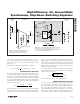
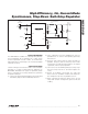
An external tracking reference with steady-state value
between 0V and V
IN
- 1.8V can be applied to SS/REFIN.
In this case, connect an RC network from external track-
ing reference and SS/REFIN, as shown in Figure 4. The
recommended value for R
SS
is approximately 1kI. R
SS
is needed to ensure that, during hiccup period, SS/
REFIN can be internally pulled down.
When an external reference is connected to SS/REFIN,
the soft-start must be provided externally.
Figure 4. RC Network for External Reference at SS/REFIN
C
SS
R
SS
V
REF_EXT
SS/REFIN
MAX15058