
Datasheet


High-Efficiency, 3A, Current-Mode
Synchronous, Step-Down Switching Regulator
MAX15058
______________________________________________________________________________________ 17
The effect of the inner current loop at higher frequen-
cies is modeled as a double-pole (complex conjugate)
frequency term, G
SAMPLING
(s), as shown:
( )
( )
SAMPLING
2
2
SW C
SW
1
G s
s s
1
f Q
f
=
+ +
π × ×
π ×
where the sampling effect quality factor, Q
C
, is:
( )
C
S
1
Q
K 1 D 0.5
=
π × × − −
And the resonant frequency is:
ω
SAMPLING
(s) = π × f
SW
or:
SW
SAMPLING
f
f
2
=
Having defined the power modulator’s transfer function,
the total system transfer can be written as follows (see
Figure 3):
Gain(s) = G
FF
(s) × G
EA
(s) × G
MOD
(DC) × G
FILTER
(s) ×
G
SAMPLING
(s)
where:
( )
( )
( )
FF
FF
FF
sC R1 1
R2
G s
R1 R2
sC R1||R2 1
+
= ×
+
+
Leaving C
FF
empty, G
FF(s)
becomes:
( )
FF
R2
G s
R1 R2
=
+
Also:
( )
( )
C C
AVEA(dB)/20
EA
AVEA(dB)/20
C C
MV
sC R 1
G s 10
10
sC R 1
g
+
= ×
+ +
which simplifies to:
( )
( )
C C
AVEA(dB)/20
EA
AVEA(dB)/20
C
MV
sC R 1
G s 10
10
sC 1
g
+
= ×
+
AVEA(dB)/20
C
MV
10
when R
g
<<
( )
( )
( )
OUT
FILTER LOAD
1
S
OUT
LOAD SW
sC ESR 1
G s R
K 1 D 0.5
1
sC 1
R f L
−
+
= ×
× − −
+ +
×
The dominant poles and zeros of the transfer loop gain
are shown below:
( )
( )
MV
P1
AVEA(dB)/20
C
P2
S
1
OUT
LOAD SW
P3 SW
Z1
C C
Z2
OUT
g
f
2 10 C
1
f
K 1 D 0.5
1
2 C
R f L
1
f f
2
1
f
2 C R
1
f
2 C ESR
−
=
π × ×
=
× − −
π × +
×
=
=
π ×
=
π ×
The order of pole-zero occurrence is:
P1 P2 Z1 CO P3 Z2
f f f f f f< ≤ < ≤ <
Under heavy load, f
P2
, approaches f
Z1
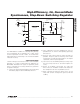
. Figure 3 shows
a graphical representation of the asymptotic system
closed-loop response, including dominant pole and zero
locations.
The loop response’s fourth asymptote (in bold, Figure 3)
is the one of interest in establishing the desired cross-
over frequency (and determining the compensation
component values). A lower crossover frequency pro-
vides for stable closed-loop operation at the expense of
a slower load- and line-transient response. Increasing
the crossover frequency improves the transient response
at the (potential) cost of system instability. A standard
rule of thumb sets the crossover frequency between
1/10 and 1/5 of the switching frequency. First, select
the passive power and decoupling components that
meet the application’s requirements. Then, choose the
small-signal compensation components to achieve the
desired closed-loop frequency response and phase
margin as outlined in the Closing the Loop: Designing
the Compensation Circuitry section.
Closing the Loop: Designing the
Compensation Circuitry
1) Select the desired crossover frequency. Choose f
CO
approximately 1/10 to 1/5 of the switching frequency
(f
SW
).
2) Determine R
C
by setting the system transfer’s fourth
asymptote gain equal to unity (assuming f
CO
> f
Z1
,
f
P2
, and f
P1
) where: