
Datasheet


Maxim Integrated
│
8
www.maximintegrated.com
MAX14970 Ruggedized 6Gbps SATA Redriver with High ESD
and Extended Temperature Operation
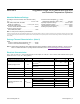
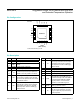
Functional Diagram/Truth Table
Detailed Description
The MAX14970 consists of two identical buffers that take
SATA input signals and return them to full SATA compliant
output levels. Each buffer includes an equalizer, a limiting
amplifier, and an output driver with preemphasis. The buf-
fer outputs are protected from high-voltage electrostatic
discharge (ESD) to Q8kV Human Body Model (HBM).
Input/Output Terminations
Inputs and outputs are internally 50I terminated and
must be AC-coupled to the SATA controller IC and SATA
device for proper operation.
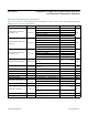
OOB Signal Detection
The device provides full OOB signal support through high-
speed, OOB-detection circuitry. SATA OOB differential
input signals of V
OOB_TH_LOW
or less are detected as
off and are not passed to the output. This prevents the
system from responding to unwanted noise. SATA OOB
differential input signals of V
OOB_TH_HIGH
or more are
detected as on and passed to the output. This allows
OOB signals to transmit through the device. The time
for the OOB detection circuit to detect an inactive SATA
OOB input and squelch the associated output, or detect
an active SATA OOB input and enable the output, is 3ns
(typ). The MODE pin can be used to program the OOB
detection range. When MODE = GND, the SATA version
3.0 range is used. When MODE = V
CC
, the SATA version
2.6 range is used.
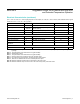
Enable Input
The device features an active-high enable input (EN). EN
has an internal pulldown resistor of 390kI (typ). Drive EN
low or leave unconnected to place the device into low-
power standby mode. In standby, the buffers are disabled,
reducing the supply current to 20µA (typ). Drive EN high
for normal operation.
50Ω50Ω
V
CC
V
CC
V
CC
V
CC
50Ω50Ω
50Ω50Ω50Ω50Ω
CONTROL LOGIC
AOUTP
AINP
AOUTM
AINM
BINM
BOUTM
BINP
BOUTP
GND MODE
V
CC
MAX14970
PA PB EN CAD
MODE
V
OOB_TH_LOW
(mV
P-P
)V
OOB_TH_HIGH
(mV
P-P
)
0
75 200
1
50 150
EN
0
1
1
1
1
PA
X
0
1
0
1
PB
X
0
0
1
1
CHANNEL A CHANNEL B
STANDBY STANDBY
STANDARD SATA STANDARD SATA
PREEMPHASIS STANDARD SATA
STANDARD SATA PREEMPHASIS
PREEMPHASIS
EN
CAD
PREEMPHASIS
STATUS
0
0 LOW-POWER STANDBY
0
1 LOW-POWER STANDBY
1
0 ACTIVE
1
1 LOW-POWER STANDBY
NOTE:
PA, PB, EN, AND MODE HAVE A 390kΩ RESISTOR PULLDOWN TO GND.
CAD HAS A 390k
Ω RESISTOR PULLUP TO V
CC
.
X = DON'T CARE.