
Datasheet


Maxim Integrated
│
7
www.maximintegrated.com
MAX14970 Ruggedized 6Gbps SATA Redriver with High ESD
and Extended Temperature Operation
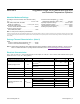
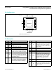
Pin Conguration
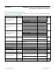
Pin Description
PIN NAME FUNCTION
1 AINP Noninverting Input, Channel A
2 AINM Inverting Input, Channel A
3, 13,
17
GND Ground
4 BOUTM Inverting Output, Channel B
5 BOUTP Noninverting Output, Channel B
6, 10,
16,
20
V
CC
Positive Supply Voltage Input. Bypass V
CC
to GND with 1µF and 0.01µF capacitors in
parallel as close as possible to the device.
7 EN
Active-High Enable Input. Drive EN low to
put the device in standby mode. Drive EN
high for normal operation. EN has a 390kΩ
(typ) pulldown resistor.
8 PB
Channel B Preemphasis-Enable Input.
Drive PB high to enable channel B output
preemphasis. Drive PB low for standard
SATA output level. PB has a 390kΩ (typ)
pulldown resistor.
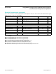
PIN NAME FUNCTION
9 PA
Channel A Preemphasis-Enable Input.
Drive PA high to enable channel A output
preemphasis. Drive PA low for standard
SATA output level. PA has a 390kΩ (typ)
pulldown resistor.
11 BINP Noninverting Input, Channel B
12 BINM Inverting Input, Channel B
14 AOUTM Inverting Output, Channel A
15 AOUTP Noninverting Output, Channel A
18 CAD
Active-Low Cable-Detect Input. For external
SATA applications, drive CAD high to put
the device in standby mode. Drive CAD low
for normal operation. CAD has a 390kI
(typ) pullup resistor. For internal SATA
applications, connect CAD to ground.
19 MODE
OOB Threshold Level Set. MODE has a
390kΩ (typ) pulldown resistor.
— EP
Exposed Pad. Internally connected to
GND. EP must be electrically connected
to a ground plane for proper thermal and
electrical operation.
19
20
18
17
7
6
8
AINM
BOUTP
9
AINP
AOUTM
BINM
BINP
AOUTP
12
CAD
45
15 14 12 11
MODE
V
CC
PA
PB
EN
V
CC
+
GND
GND
3
13
GND
16
10
V
CC
V
CC
TQFN
(4mm × 4mm)
MAX14970
TOP VIEW
BOUTM
*CONNECT EXPOSED PAD (EP) TO GND.
*EP