
Datasheet


4 Maxim Integrated
40Mbps, +3.3V, RS-485 Half-Duplex
Transceivers
MAX14840E/MAX14841E
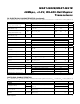
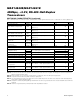
SWITCHING CHARACTERISTICS (continued)
(V
CC
= +3.0V to +3.6V, T
A
= -40NC to +125NC, unless otherwise noted. Typical values are at V
CC
= +3.3V and T
A
= +25NC.) (Notes 2, 3)
Note 2:
All devices are 100% production tested at T
A
= +25NC. Specifications for all temperature limits are guaranteed by design.
Note 3: All currents into the device are positive; all currents out of the device are negative. All voltages are referenced to device
ground, unless otherwise noted.
Note 4: DV
OD
and DV
OC
are the changes in V
OD
and V
OC
, respectively, when the DI input changes state.
Note 5: Capacitive load includes test probe and fixture capacitance.
Note 6: The timing parameter refers to the driver or receiver enable delay when the device has exited the initial hot-swap protect
state and is in normal operating mode.
Note 7: Shutdown is enabled by driving RE high and DE low. The device is guaranteed to have entered shutdown after t
SHDN
has
elapsed.
Note 8: Parameter is guaranteed by characterization and not production tested.
PARAMETER SYMBOL CONDITIONS MIN TYP MAX UNITS
Maximum Data Rate DR
MAX
40 Mbps
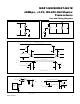
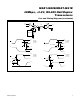
Driver Enable to Output High t
DZH
R
L
= 110I, C
L
= 50pF, Figures 4 and 5
(Notes 5, 6)
30 ns
Driver Enable to Output Low t
DZL
R
L
= 110I, C
L
= 50pF, Figures 4 and 5
(Notes 5, 6)
30 ns
Driver Disable Time from Low t
DLZ
R
L
= 110I, C
L
= 50pF, Figures 4 and 5
(Notes 5, 6)
30 ns
Driver Disable Time from High t
DHZ
R
L
= 110I, C
L
= 50pF, Figures 4 and 5
(Notes 5, 6)
30 ns
Driver Enable from Shutdown to
Output Low
t
DZL(SHDN)
R
L
= 110I, C
L
= 50pF, Figures 4 and 5
(Notes 5, 6)
4
Fs
Driver Enable from Shutdown to
Output High
t
DZH(SHDN)
R
L
= 110I, C
L
= 50pF, Figures 4 and 5
(Notes 5, 6)
4
Fs
Time to Shutdown t
SHDN
(Note 7) 50 800 ns
RECEIVER
Propagation Delay
t
RPLH
C
L
= 15pF, Figures 6 and 7 (Note 5)
25
ns
t
RPHL
25
Receiver Output Skew t
RSKEW
C
L
= 15pF, Figures 6 and 7 (Notes 5, 8) 2 ns
Maximum Data Rate DR
MAX
40 Mbps
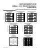
Receiver Enable to Output High t
RZH
R
L
= 1kI, C
L
= 15pF, Figure 8 (Notes 5, 6)
20 ns
Receiver Enable to Output Low t
RZL
R
L
= 1kI, C
L
= 15pF, Figure 8 (Notes 5, 6)
20 ns
Receiver Disable Time from Low t
RLZ
R
L
= 1kI, C
L
= 15pF, Figure 8 (Notes 5, 6)
20 ns
Receiver Disable Time from High t
RHZ
R
L
= 1kI, C
L
= 15pF, Figure 8 (Notes 5, 6)
20 ns
Receiver Enable from Shutdown
to Output Low
t
RZL(SHDN)
R
L
= 1kI, C
L
= 15pF, Figure 8 (Notes 5, 6)
4
Fs
Receiver Enable from Shutdown
to Output High
t
RZH(SHDN)
R
L
= 1kI, C
L
= 15pF, Figure 8 (Notes 5, 6)
4
Fs
Time to Shutdown t
SHDN
(Note 7) 50 800 ns