
Datasheet


MAX1407/MAX1408/MAX1409/MAX1414
Low-Power, 16-Bit Multichannel DAS with
Internal Reference,10-Bit DACs, and RTC
______________________________________________________________________________________ 43
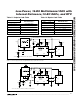
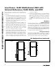
counter electrode is configured as a transimpedance
amplifier to measure the current. Figure 25 shows a three
electrode potentiostat application that is driven at all the
electrodes and measured at the working electrode. With
this application, the DAC connected to the working elec-
trode sets the bias voltage relative to the reference elec-
trode and also measures the current that the sensor pro-
duces. The DAC connected to the reference and counter
electrodes takes advantage of the force/sense outputs to
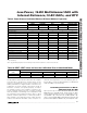
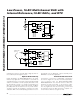
Figure 23. Self-Biased Two Electrode Potentiostat Application
MAX1407
MAX1409
MAX1414
IN0
AUX.
VOLTAGE
INPUTS
REF
IN1
IN2
IN3
ALL I/O AVAILABLE AS INPUTS TO ADC AND COMPARATOR.
MAX1409 HAS IN0, OUT1, FB1, AND REF ONLY.
BAND
GAP
FB1
REF
OUT1
I
F
R
F
SENSOR
WE
CE
4.7µF
BUF
10-BIT DAC
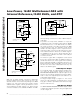
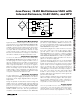
Figure 24. Driven Two Electrode Potentiostat Application
MAX1407
MAX1414
IN0
AUX.
VOLTAGE
INPUTS
REF
IN1
IN2
IN3
ALL I/O AVAILABLE AS INPUTS TO ADC AND COMPARATOR.
BAND
GAP
FB1
FB2
REF
REF
OUT1
OUT2
I
F
R
F
SENSOR
WE
CE
4.7µF
BUF
10-BIT DAC
10-BIT DAC
Figure 25. Driven Three Electrode Potentiostat Application
MAX1407
MAX1414
IN0
AUX.
VOLTAGE
INPUTS
REF
IN1
IN2
IN3
ALL I/O AVAILABLE AS INPUTS TO ADC AND COMPARATOR.
BAND
GAP
FB1
FB2
REF
REF
OUT1
OUT2
I
F
R
F
SENSOR
WE
CE
RE
4.7µF
BUF
10-BIT DAC
10-BIT DAC
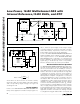
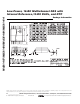
Figure 26. Optical Reflectometry Application
MAX1407
MAX1414
IN0
AUX.
VOLTAGE
INPUTS
REF
IN1
IN2
IN3
ALL I/O AVAILABLE AS INPUTS TO ADC AND COMPARATOR.
BAND
GAP
FB1
FB2
REF
REF
OUT1
LED
QB
PHOTO-
DIODE
V
BAT
OUT2
R
B
4.7µF
BUF
10-BIT DAC
10-BIT DAC
I
F
R
F