
Datasheet


MAX1407/MAX1408/MAX1409/MAX1414
Low-Power, 16-Bit Multichannel DAS with
Internal Reference,10-Bit DACs, and RTC
42 ______________________________________________________________________________________
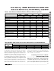
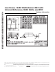
where NB is the decimal value of the DAC’s binary
input code. Table 12 shows digital codes (offset binary)
and corresponding output voltages for Figure 18
assuming R1 = R2.
Power Supplies
Power to the MAX1407/MAX1408/MAX1409/MAX1414
family can be supplied in a number of ways. Figures 19,
20, 21, and 22 are power-supply circuits using a step-up
converter, buck-boost converter, step-down converter,
and a direct battery, respectively. Choose the correct
power-supply circuit for your specific application.
Connect the MAX1407/MAX1408/MAX1409/MAX1414
AV
DD
and DV
DD
power supplies together. While the
latch-up performance of the MAX1407/MAX1408/
MAX1409/MAX1414 is adequate, it is important that
power is applied to the device before the analog input
signals (IN_) to avoid latch-up. If this is not possible,
limit the current flow into any of these pins to 50mA.
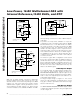
Electrochemical Sensor Operation
The MAX1407/MAX1408/MAX1409/MAX1414 family inter-
face with electrochemical sensors. The 10-bit DACs with
the force/sense buffers have the flexibility to connect to
many different types of sensors. Figure 23 shows how to
interface with a two electrode potentiostat. A single DAC
is required to set the bias across the sensor relative to
ground and an external precision resistor completes the
transimpedance amplifier configuration to convert the
current generated by the sensor to a voltage to be mea-
sured by the ADC. The induced error from this source is
negligible due to FB1’s extremely low input bias current.
Internally, the ADC can differentially measure directly
across the external transimpedance resistor, R
F
, eliminat-
ing any errors due to voltages drifting over time, tempera-
ture, or supply voltage. Figure 24 shows a two electrode
potentiostat application that is driven at the working elec-
trode and measured at the counter electrode. With this
application, the DAC connected to the working electrode
is configured in unity gain and the DAC connected to the
VV
OUT REF
=
−
2
1024
1
NB
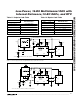
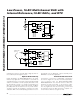
Figure 21. Power-Supply Circuit Using MAX640 Step-Down DC-DC Converter
MAX1407
MAX1408
MAX1409
MAX1414
MAX640
V+
D1
IN0
RESET RESET
µP/µC
WU1 INPUT
100µF
0.1µF 0.1µF
0.1µF
R
33µF
*ONE TRANSISTOR (9V), ONE J CELL (6V), OR FOUR ALKALINE CELLS
E1*
V
BAT
V
DD
(+3.3V)
100µH
2R
SHDN
LX
VOUT
VFBLBI GND
CPLL
AGND DGND
18nF
AV
DD
DV
DD
V
DD
V
SS
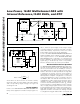
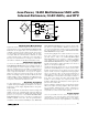
Figure 22. Power-Supply Circuit Using Direct Battery Connection
MAX1407
MAX1408
MAX1409
MAX1414
RESET RESET
µP/µC
WU1 INPUT
10µF
0.1µF
0.1µF
0.1µF
*ONE Li+ COIN OR TWO BUTTON CELLS
E1*
CPLL
AGND DGND
18nF
AV
DD
V
BAT
DV
DD
V
DD
V
SS