
Datasheet


MAX1407/MAX1408/MAX1409/MAX1414
Low-Power, 16-Bit Multichannel DAS with
Internal Reference,10-Bit DACs, and RTC
40 ______________________________________________________________________________________
(BIP = 0). To initiate an ADC conversion: 1) Enter Run
mode by addressing the Run register 2) Select the
desired channels for conversion by writing to the MUX
register, (e.g., 94h selects IN1 for the positive channel
and IN2 for the negative channel) 3) Initiate the conver-
sion by writing to the ADC register, (e.g., 01h). The first
conversion result becomes available in 100ms. The ADC
will keep doing conversions at a rate of 30Hz until pow-
ered down.
To perform an on-chip offset calibration on a specific
configuration, write to the ADC register with the MODE
bit and STA1 bit set to 1. The ADC will do one calibra-
tion using the inputs to the ADC specified in the MUX
register and then stop. The calibration result will be
stored in the Offset register in two’s complement form.
Subsequent ADC conversion results will have the offset
value subtracted before written to the DATA register.
The MODE bit will be reset to 0 automatically upon
completion of the calibration. The ADC is now ready for
a normal conversion.
The offset for a given ADC configuration can be stored
by the µP to avoid another ADC recalibration. Write the
stored offset back to the offset register when returning
back to that particular ADC configuration where the cal-
ibration was taken. Subsequent ADC conversion results
will have the offset value subtracted before they are
written to the DATA register.
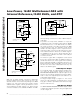
DAC Unipolar Output
For a unipolar output, the output voltages and the refer-
ence have the same polarity. Figure 16 shows the
MAX1407/MAX1409/MAX1414s’ unipolar output circuit,
which is also the typical operating circuit for the DACs.
Table 11 lists some unipolar input codes and their cor-
responding output voltages.
For larger output swing see Figure 17. This circuit
shows the output amplifiers configured with a closed-
loop gain of +2V/V to provide 0 to 2.5V full-scale range
with the 1.25V reference.
DAC Bipolar Output
The MAX1407/MAX1409/MAX1414 DAC outputs can be
configured for bipolar operation using the application
circuit on Figure 18:
Figure 16. Unipolar Output Circuit
MAX1407/MAX1409/MAX1414
THE MAX1409 HAS ONE DAC
V
REF
= 1.25V
FB1
REF
FB2
OUT1
OUT2
AGND
DGND
DAC 1
DAC 2
Figure 17. Unipolar Rail-to-Rail Output Circuit
MAX1407/MAX1409/MAX1414
THE MAX1409 HAS ONE DAC
V
REF
= 1.25V
FB1
10kΩ
10kΩ
REF
FB2
OUT1
OUT2
AGND
DGND
DAC 1
10kΩ
10kΩ
DAC 2
Figure 18. Bipolar Output Circuit
MAX1407/MAX1409/MAX1414
+5V
-5V
FB_
R1 R2
R2 = R1
REF
OUT_
DAC_
V
OUT