
Datasheet


MAX1407/MAX1408/MAX1409/MAX1414
Low-Power, 16-Bit Multichannel DAS with
Internal Reference,10-Bit DACs, and RTC
______________________________________________________________________________________ 39
tor spreads the transient-load current from the sampler
over time due to the RC time constant of the circuit.
However, an improperly chosen series resistance can
hinder performance in high-resolution converters. The
settling time of the RC network can limit the speed at
which the converter can operate properly, or reduce
the settling accuracy of the sampler. In practice, this
means ensuring that the RC time constant, resulting
from the product of the driving source impedance and
the capacitance presented by both the device’s input
and any external capacitance is sufficiently small to
allow settling to the desired accuracy. Table 10 sum-
marizes the maximum allowable series resistance vs.
external shunt capacitance for each different gain set-
ting in order to ensure 16-bit performance in unbuffered
mode (for 60sps conversion rate).
Performing a Conversion or Offset-
Calibration with the ADC
Upon power-up, the MAX1407/MAX1408/MAX1409/
MAX1414 are in Standby mode. At this point, the ADC
register default settings are set for a normal ADC conver-
sion (MODE = 0), conversion rate of 30Hz (RATE = 0),
gain of 1/3 V/V (GAIN [00]), input buffers bypassed and
powered down (BUFP = BUFN = 0), and unipolar mode
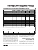
Table 9. Power States of Individual Blocks at Different Modes of Operation
POWER MODES
CIRCUIT BLOCKS
SLEEP STANDBY IDLE RUN WA K E- U P EVEN T
Serial Interface xxxx x
Wake-Up Circuitry xxxx x
Crystal Oscillator xxxx x
RTC with Alarm xxxx x
RESET Voltage Monitor xxxx x
Low V
DD
Voltage Monitor — xxx x
Master Bias Circuit — xxx x
PLL — xxx x
FOUT — xxx x
SHDN = High — xxx x
DAC1 —— x x N/A
DAC2 —— x x N/A
Bandgap —— x x N/A
Bandgap Buffer —— x x N/A
Signal Detect Comparator —— x x N/A
ADC Multiplexer —— x x N/A
ADC Input Buffers ——— x N/A
ADC ——— x N/A
x = powered-up
N/A = programming the parts into the wake-up mode would not alter the content of these blocks
Table 10. REXT, CEXT Values for Less than 16-Bit Gain Error in Unbuffered Mode
EXTERNAL RESISTANCE R
EXT
(kΩ)
PGA GAIN
(V/V)
C
EXT
= 0pF C
EXT
= 50pF C
EXT
= 100pF C
EXT
= 200pF C
EXT
= 500pF
1 194 56 33 19 9
2 100 30 16 9 4.5