
Datasheet


MAX1407/MAX1408/MAX1409/MAX1414
Low-Power, 16-Bit Multichannel DAS with
Internal Reference,10-Bit DACs, and RTC
30 ______________________________________________________________________________________
AL_BURST REGISTER (01000)
Writing to this register begins the alarm burst mode
transfer. All the alarm clock registers are consecutively
read from or written to starting with Bit7 of the Al_Sec
register followed by the Al_Min register, Al_Hour regis-
ter, and finally the Al_Day register.
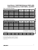
Table 7. Common Mask Bits Combinations
ALARM REGISTER MASK BITS (BIT 7)
AL_SEC AL_MIN M_HOUR M_DAY
FUNCTION HOW OFTEN?
1 1 1 1 Alarm occurs once per second Once per second
0 1 1 1 Alarm occurs when seconds match Once per minute
001 1
Alarm occurs when minutes and
seconds match
Once per hour
000 1
Alarm occurs when hours, minutes, and
seconds match
Once per day
000 0
Alarm occurs when day, hours, minutes,
and seconds match
Once per week
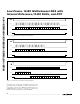
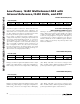
M_SEC: Alarm mask bit. A logic 1 masks out the sec-
onds alarm comparator.
10SEC[2:0]: These are the 10-second bits (0–50 sec-
onds) of the alarm.
SEC[3:0]: These are the second bits (0–9 seconds) of
the alarm.
FIRST BIT (MSB) (LSB)
NAME M_SEC 10SEC2 10SEC1 10SEC0 SEC3 SEC2 SEC1 SEC0
DEFAULT 0 0 000000
AL_SEC REGISTER (01001)
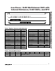
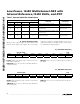
M_MIN: Alarm mask bit. A logic 1 masks out the minute
alarm comparator.
10MIN[2:0]: These are the 10-minute bits (0–50 min-
utes) of the alarm.
MIN[3:0]: These are the minute bits (0–9 minutes) of
the alarm.
FIRST BIT (MSB) (LSB)
NAME M_MIN 10MIN2 10MIN1 10MIN0 MIN3 MIN2 MIN1 MIN0
DEFAULT 0 0 000000
AL_MIN REGISTER (01010)