
Datasheet


MAX1280/MAX1281
400ksps/300ksps, Single-Supply, Low-Power, 8-Channel,
Serial 12-Bit ADCs with Internal Reference
16 ______________________________________________________________________________________
progress. In software power-down mode, the serial
interface remains active, waiting for a new control byte
to start conversion and switch to full-power mode.
Once the conversion is completed, the device goes
into the programmed power mode until a new control
byte is written.
The power-up delay is dependent on the power-down
state. Software low-power modes will be able to start
conversion immediately when running at decreased
clock rates (see Power-Down Sequencing). During
power-on reset, when exiting software full power-down
mode or exiting hardware shutdown, the device goes
immediately into full-power mode and is ready to con-
vert after 2µs when using an external reference. When
using the internal reference, wait for the typical power-
up delay from a full power-down (software or hard-
ware), as shown in Figure 9.
Software Power-Down
Software power-down is activated using bits PD1 and
PD0 of the control byte. When software shutdown is
asserted, the ADC completes the conversion in
progress and powers down into the specified low-
quiescent-current state (2µA, 0.9mA, or 1.3mA).
The first logic 1 on DIN is interpreted as a start bit and
puts the MAX1280/MAX1281 into their full-power mode.
Following the start bit, the data input word or control
byte also determines the next power-down state. For
example, if the DIN word contains PD1 = 0 and PD0 =
1, a 0.9mA power-down starts after the conversion.
112
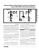
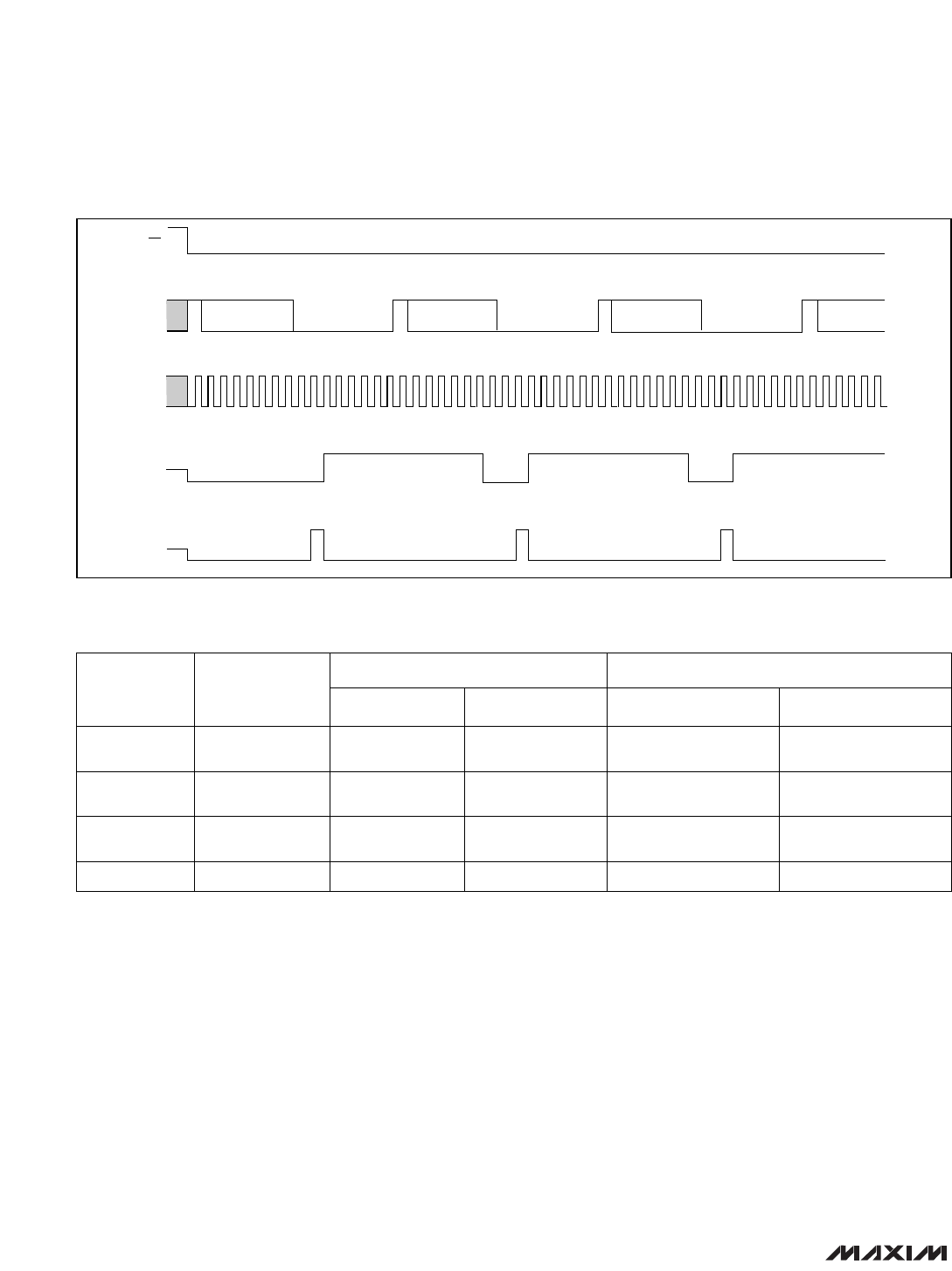
B11 B6 B0 B11 B6 B0 B11 B6
168 1 12 1685 1 12 16851
SETCS CONTROL BYTE 2S CONTROL BYTE 1SDIN
SCLK
DOUT
SSTRB
CS
CONTROL BYTE 0
CONVERSION RESULT 0 CONVERSION RESULT 1
5
HIGH-Z
HIGH-Z
Figure 8. Continuous 16-Clock/Conversion Timing
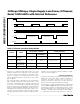
PD1/PD0 MODE
CONVERTING
AFTER
CONVERSION
INPUT COMPARATOR REFERENCE
00
Full Power-Down
(FULLPD)
2.5mA 2µA Off Off
01
Fast Power-Down
(FASTPD)
2.5mA 0.9mA Reduced Power On
10
Reduced-Power
Mode (REDPD)
2.5mA 1.3mA Reduced Power On
11 Operating Mode 2.5mA 2.0mA Full Power On
CIRCUIT SECTIONS*TOTAL SUPPLY CURRENT
Table 4. Software-Controlled Power Modes
*Circuit operation between conversions; during conversion, all circuits are fully powered up.