
Datasheet


MAX1253/MAX1254
Stand-Alone, 10-Channel, 12-Bit System Monitors
with Internal Temperature Sensor and V
DD
Monitor
_______________________________________________________________________________________ 5
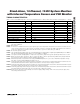
Note 1: Relative accuracy is the deviation of the analog value at any code from its theoretical value after the gain and offset errors
have been calibrated.
Note 2: Offset nulled.
Note 3: In reference mode 00, the reference system powers up for each temperature measurement. In reference mode 01, the ref-
erence system powers up once per sequence of channels scanned. If a sample wait <80µs is programmed, the reference
system is on all the time. In reference mode 10, the reference system is on all the time (see Table 7).
Note 4: No external capacitor on REF.
Note 5: The operational input voltage range for each individual input of a differentially configured pair (AIN0–AIN7) is from GND to
V
DD
.
The operational input voltage difference is from -V
REF
/2 to +V
REF
/2.
Note 6: See Figure 3 and the Sampling Error vs. Input Source Impedance graph in the Typical Operating Characteristics section.
Note 7: Grade A tested at +10°C and +55°C. -20°C to +85°C and -40°C to +85°C specifications guaranteed by design. Grade B
tested at +25°C. T
MIN
to T
MAX
specification guaranteed by design.
Note 8: External temperature measurement mode using an MMBT3904 (Diodes Inc.) as a sensor. External temperature sensing
from -40°C to +85°C; MAX1253/MAX1254 held at +25°C.
Note 9: Performing eight single-ended external channels’ temperature measurements, an internal temperature measurement, and
an internal V
DD
measurement with no sample wait results in a conversion rate of 2ksps per channel.
Note 10: Performing eight single-ended voltage measurements, an internal temperature measurement, and an internal V
DD
measure-
ment with no sample wait results in a conversion rate of 7ksps per channel.
Note 11: Performing eight single-ended voltage measurements, an internal temperature measurement, and an internal V
DD
measure-
ment with maximum sample wait results in a conversion rate of 3ksps per channel.
Note 12: Defined as the shift in the code boundary as a result of supply voltage change. V
DD
= min to max; full-scale input, mea-
sured using external reference.
TIMING CHARACTERISTICS
(V
DD
= +2.7V to +3.6V (MAX1253), V
DD
= +4.5V to +5.5V (MAX1254), T
A
= T
MIN
to T
MAX
, unless otherwise noted.) (Figures 1, 2, and 4)
PARAMETER SYMBOL CONDITIONS MIN TYP MAX UNITS
SCLK Clock Period t
CP
100 0.5 ns
SCLK Pulse Width High Time t
CH
45 ns
SCLK Pulse Width Low Time t
CL
45 ns
DIN to SCLK Setup Time t
DS
25 ns
DIN to SCLK Hold Time t
DH
0ns
CS Fall to SCLK Rise Setup t
CSS
25 ns
SCLK Rise to CS Rise Hold t
CSH
50 ns
SCLK Fall to DOUT Valid t
DOV
C
L
= 30pF 50 ns
CS Rise to DOUT Disable t
DOD
C
L
= 30pF 40 ns
CS Fall to DOUT Enable t
DOE
C
L
= 30pF 40 ns
CS Pulse Width High t
CSW
40 ns