
Datasheet


MAX1236–MAX1239
(FIFO) sequence. If AIN_/REF is set to be a reference
input or output (SEL1 = 1, Table 6), AIN_/REF is exclud-
ed from a multichannel scan. The memory contents can
be read continuously. If reading continues past the
result stored in memory, the pointer wraps around and
point to the first result. Note that only the current con-
version results is read from memory. The device must
be addressed with a read command to obtain new con-
version results.
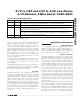
The internal clock mode’s clock stretching quiets the
SCL bus signal reducing the system noise during con-
version. Using the internal clock also frees the bus
master (typically a microcontroller) from the burden of
running the conversion clock, allowing it to perform
other tasks that do not need to use the bus.
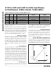
External Clock
When configured for external clock mode (CLK = 1),
the MAX1236–MAX1239 use the SCL as the conversion
2.7V to 3.6V and 4.5V to 5.5V, Low-Power,
4-/12-Channel, 2-Wire Serial, 12-Bit ADCs
16 ______________________________________________________________________________________
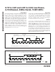
B. SCAN MODE CONVERSIONS WITH INTERNAL CLOCK
S
1
SLAVE ADDRESS A
711
R
CLOCK STRETCH
NUMBER OF BITS
P or Sr
1
8
RESULT 8 LSBs
8
RESULT 4 MSBs A
A
1
A. SINGLE CONVERSION WITH INTERNAL CLOCK
S
1
SLAVE ADDRESS
711
R
CLOCK STRETCH
A
NUMBER OF BITS
P or Sr
1
8
RESULT 1 ( 4MSBs) A
1
A
8
RESULT 1 (8 LSBs)
A
8
RESULT N (8LSBs)
A
1
8
RESULT N (4MSBs)
SLAVE TO MASTER
MASTER TO SLAVE
CLOCK STRETCH
t
ACQ1
t
CONV2
t
ACQ2
t
CONVN
t
ACQN
t
CONV
t
ACQ
11
t
CONV1
Figure 10. Internal Clock Mode Read Cycles
SLAVE ADDRESS
t
CONV1
t
ACQ1
t
ACQ2
t
CONVN
t
ACQN
t
CONV
t
ACQ
NUMBER OF BITS
NUMBER OF BITS
18
A
1
S
1
A
711
R
S
1
711
R
P OR Sr
1
8
A
1
A
8
A
8
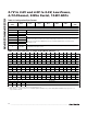
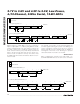
B. SCAN MODE CONVERSIONS WITH EXTERNAL CLOCK
11
SLAVE ADDRESS P OR SrRESULT (8 LSBs)
8
A
1
RESULT (4 MSBs)
A. SINGLE CONVERSION WITH EXTERNAL CLOCK
SLAVE TO MASTER
MASTER TO SLAVE
RESULT 1 (4 MSBs) RESULT 2 (8 LSBs) RESULT N (8 LSBs)
A
1
8
RESULT N (4 MSBs)
A
Figure 11. External Clock Mode Read Cycle