
Datasheet


18 _____________________________________________________________________________________
MAX11661–MAX11666
500ksps, Low-Power,
Serial 12-/10-/8-Bit ADCs
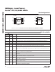
Pin Description
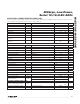
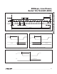
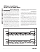
Pin Configurations
*CONNECT EP TO GROUND PLANE. DEVICES DO NOT OPERATE WHEN EP IS NOT CONNECTED TO GROUND!
EP*
TOP VIEW
+
TOP VIEW
GND
SCLKAIN
16CS
5 DOUT
V
DD
MAX11661
MAX11663
MAX11665
SOT23
2
34
+
µMAX
29DOUTAIN2
110 SCLKAIN1
OVDDAGND 38
CHSELREF 7
CSV
DD
6
MAX11662
MAX11664
MAX11666
4
5
PIN
NAME FUNCTION
µMAX SOT23
1 — AIN1
Analog Input Channel 1. Single-ended analog input with respect to AGND with range of 0V to
V
REF
.
2 — AIN2
Analog Input Channel 2. Single-ended analog input with respect to AGND with range of 0V to
V
REF.
— 3 AIN Analog Input Channel. Single-ended analog input with respect to GND with range of 0V to V
DD
.
— 2 GND Ground. Connect GND to the GND ground plane.
3 — AGND Analog Ground. Connect AGND directly the GND ground plane.
4 — REF
External Reference Input. REF defines the signal range of the input signal AIN1/AIN2: 0V to V
REF
.
The range of V
REF
is 1V to V
DD.
Bypass REF to AGND with 10FF || 0.1FF capacitor.
5 1 V
DD
Positive Supply Voltage. Bypass V
DD
with a 10FF || 0.1FF capacitor to GND. V
DD
range is 2.2V
to 3.6V. For the SOT23 package, V
DD
also defines the signal range of the input signal AIN: 0V to
V
DD
.
6 6
CS
Active-Low Chip-Select Input. The falling edge of CS samples the analog input signal, starts a
conversion, and frames the serial-data transfer.
7 — CHSEL
Channel Select. Set CHSEL high to select AIN2 for conversion. Set CHSEL low to select AIN1 for
conversion.
8 — OVDD
Digital Interface Supply for SCLK, CS, DOUT, and CHSEL. The OVDD range is 1.5V to V
DD
.
Bypass OVDD with a 10FF || 0.1FF capacitor to GND.
9 5 DOUT
Three-State Serial-Data Output. ADC conversion results are clocked out on the falling edge of
SCLK, MSB first. See Figure 1.
10 4 SCLK
Serial-Clock Input. SCLK drives the conversion process. DOUT is updated on the falling edge of
SCLK. See Figures 2 and 3.
— — EP
Exposed Pad (µMAX Only). Connect EP directly to a solid ground plane. Devices do not operate
when EP is not connected to ground!