
Datasheet


MAX1153/MAX1154
Stand-Alone, 10-Channel, 10-Bit System Monitors
with Internal Temperature Sensor and V
DD
Monitor
______________________________________________________________________________________ 23
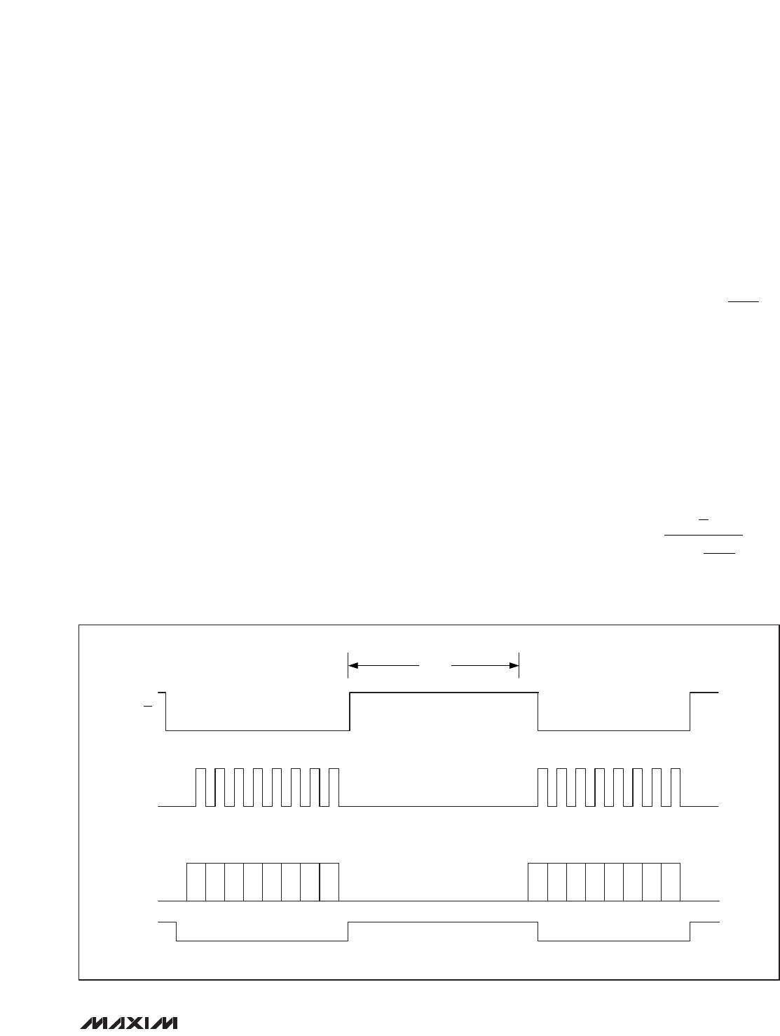
execute a manual conversion. See Figure 9 for manual
conversion timing:
1) Disable autoscan (set up register scan mode bit to
zero), if necessary.
2) Pull CS low.
3) Initiate a conversion by issuing a Manually
Triggered Conversion command (0000, followed by
the address bits of the channel to be converted).
4) Pull CS high to start the conversion.
5) Maintain a logic high on CS to allow for reference
power-up (if the reference mode requires it) and
conversion time.
6) Pull CS low.
7) Issue a Read Current Data Register for Selected-
Channel command (0010, followed by the same
address of the channel in the Manually Triggered
Conversion command).
Voltage Measurements
Every voltage measurement (internal V
DD
or external
input channel) requires 10.6µs to complete. If the inter-
nal reference needs to power up (reference mode =
01), an additional 40µs is required every time the
MAX1153/MAX1154 come out of automatic shutdown
mode after a sample wait period greater than 80µs.
Monitoring V
DD
This internal acquisition channel samples and converts
the supply voltage, V
DD
.
V
DD
value can be calculated from the digitized data
with the following equation:
The reference voltage must be larger than 1/2V
DD
for
the operation to work properly. V
DD
monitoring requires
10.6µs (typ) per measurement.
Temperature Measurement
The MAX1153/MAX1154 perform temperature measure-
ment by measuring the voltage across a diode-con-
nected transistor at two different current levels. The
following equation illustrates the algorithm used for
temperature calculations:
temperature V V x
HIGH LOW
=−
⎡
⎣
⎢
⎤
⎦
⎥
()
q
k
nxln
I
I
High
LOW
V x current data register content x
V
DD
REF
=
⎛
⎝
⎜
⎞
⎠
⎟
2
1024
(__ _ )
C3
C2 C1 C0 A2 A1 A0
SCLK
DIN
DOUT
C3 C2 C1 C0 A2 A1 A0A3A3
CS
t
PU+CONV
Figure 9. Manual Conversion Timing Without Reading Data