
Datasheet


MAX1153/MAX1154
Stand-Alone, 10-Channel, 10-Bit System Monitors
with Internal Temperature Sensor and V
DD
Monitor
18 ______________________________________________________________________________________
Write-Selected Channel Configuration
Registers (Command Code 1100)
The Write-Selected Channel Configuration Register com-
mand, 1100, writes to the three channel configuration
registers for the addressed channel (see Table 3). The
first register to be written is the upper threshold (2 bytes),
followed by the lower threshold (2 bytes), ending with the
channel configuration register (1 byte), all MSB first.
Writing to the configuration registers resets the alarm reg-
ister bits and the fault counters for the addressed chan-
nel. See the
Channel Registers
section for more details.
Write Global Configuration Registers
(Command Code 1101)
The Write Global Configuration Registers command,
1101, writes to three registers: the channel-enable reg-
ister (2 bytes), the input configuration register (2 bytes),
and the setup register (1 byte). The command address
bits are ignored. See the
Global Configuration
Registers
section for more details.
Global Configuration Registers
The global configuration registers consist of the chan-
nel-enable register, the input configuration register, and
the setup register. These registers hold configuration
data common to all channels.
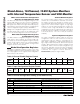
Channel-Enable Register
The channel-enable register (Table 4) controls which
channels are converted while in automatic scan mode.
The register contents are ignored for manual conver-
sion commands. Each input channel has a correspond-
ing bit in the channel-enable register. A logic high
enables the corresponding analog input channel for
conversion, while a logic low disables it. In differential
configuration, the bits for odd channels are ignored. At
power-up and after a RESET command, the register
contents default to 111111111111b (all channels
enabled).
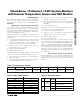
Input Configuration Register
The input configuration register (Table 5) stores the
configuration code for each channel as a 3-bit per
channel-pair code (see Table 6), selecting from five
input signal configurations: single-ended unipolar volt-
age, single-ended temperature, differential unipolar
voltage, differential bipolar voltage, and differential
temperature. Table 5 shows the input configuration reg-
ister format, and Table 6 shows the 3-bit encoding for
channel configuration. At power-up and after a RESET
command, the register contents defaults to
000000000000b (all inputs single ended).
Table 4. Channel-Enable Register Format
B11
(MSB)
B10B9B8B7B6B5B4B3B2B1
B0
(LSB)
TEMP V
DD
AIN0 AIN1 AIN2 AIN3 AIN4 AIN5 AIN6 AIN7 Res Res
Table 5. Input Configuration Register Format
B11
(MSB)
B10 B9 B8 B7 B6 B5 B4 B3 B2 B1
B0
(LSB)
AIN0 and AIN1 configuration
AIN2 and AIN3 configuration AIN4 and AIN5 configuration
AIN6 and AIN7 configuration
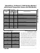
Table 6. Channel Configuration Coding (3 Bits/Channel Pair)
CODE
AIN0, AIN2, AIN4, AIN6 CONFIGURATION AIN1, AIN3, AIN5, AIN7 CONFIGURATION
000 Single-ended input (power-up state) Single-ended input (power-up state)
001 Single-ended input Single-ended, external temperature sensor input
010 Single-ended, external temperature sensor input Single-ended input
011 Single-ended, external temperature sensor input Single-ended, external temperature sensor input
100 Differential unipolar encoded, positive input Differential unipolar encoded, negative input
101 Differential bipolar encoded, positive input Differential bipolar encoded, negative input
110
Differential external temperature sensor, positive input
Differential external temperature sensor, negative input
111 Reserved Reserved