
Datasheet


MAX1153/MAX1154
Stand-Alone, 10-Channel, 10-Bit System Monitors
with Internal Temperature Sensor and V
DD
Monitor
______________________________________________________________________________________ 11
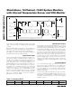
During the acquisition interval, IN+ and IN- charge both
a positive (CHOLDP) and a negative (CHOLDN) sam-
pling capacitor. After completing the acquisition inter-
val, the T/H switches open, storing an accurate sample
of the differential voltage between IN+ and IN-. This
charge is then transferred to the ADC and converted.
Finally, the conversion result is transferred to the cur-
rent data register.
Temperature conversions require 46µs (typ) and mea-
sure the difference between two sequential voltage
measurements (see the
Temperature Measurement
section for a detailed description).
Fully Differential Track/Hold (T/H)
The T/H acquisition interval begins with the rising edge
of CS (for manually triggered conversions) and is inter-
nally timed to 1.5µs (typ). The accuracy of the input sig-
nal sample is a function of the input signal’s source
impedance and the T/H’s capacitance. In order to
achieve adequate settling of the T/H, limit the signal
source impedance to a maximum of 1kΩ.
Input Bandwidth
The ADC’s input tracking circuitry has a 1MHz small-
signal bandwidth. To avoid high-frequency signals
aliasing into the frequency band of interest, anti-alias
prefiltering of the input signals is recommended.
Analog Input Protection
Internal protection diodes, which clamp the analog
inputs to V
DD
and GND, allow the channel input pins to
swing from (V
GND
- 0.3V) to (V
DD
+ 0.3V) without dam-
age. However, for accurate conversions near full scale,
the inputs must not exceed V
DD
by more than 50mV or
be lower than V
GND
by 50mV. If the analog input range
must exceed 50mV beyond the supplies, limit the input
current.
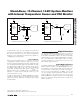
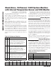
Single Ended/Differential
The MAX1153/MAX1154 use a fully differential ADC for
all conversions. Through the input configuration regis-
ter, the analog inputs can be configured for either dif-
ferential or single-ended conversions. When sampling
signal sources close to the MAX1153/MAX1154, single-
ended conversion is generally sufficient. Single-ended
conversions use only one analog input per signal
source, internally referenced to GND.
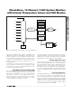
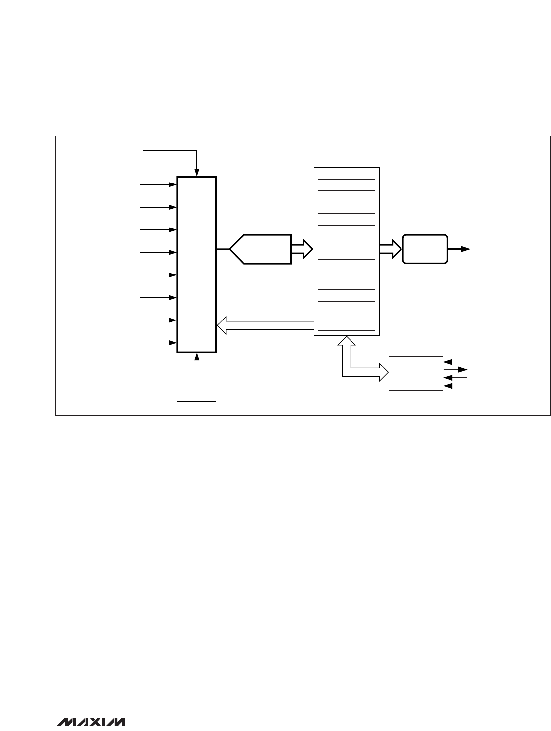
MUX
AIN 0
V
DD
AIN 1
AIN 2
AIN 3
AIN 4
AIN 5
AIN 6
AIN 7
TEMP
SENSE
12-BIT
ADC WITH T/H
DIGITAL
COMPARATOR
INPUT REGISTERS 0–10
CURRENT DATA
UPPER THRESHOLD
LOWER THRESHOLD
# FAULT CYCLES
AVERAGE
CONFIGURATION/
STATUS
REGISTERS
SCAN AND
CONVERSION
CONTROL
SERIAL
INTERFACE
DIN
INT
DOUT
SCLK
CS
Figure 3. Simplified Alarm Block Diagram of the MAX1153/MAX1154