
Datasheet


MAX1146–MAX1149
Multichannel, True-Differential,
Serial, 14-Bit ADCs
20 ______________________________________________________________________________________
edge and is clocked into the µP on SCLK’s rising edge.
The first 8-bit data stream contains the first 8-bits of
DOUT starting with the MSB. The second 8-bit data
stream contains the remaining 6 result bits.
QSPI Interface
Using the high-speed QSPI interface (Figure 17) with
CPOL = 0 and CPHA = 0, the MAX1146–MAX1149 sup-
port a maximum f
SCLK
of 2.1MHz. One 16-bit reading is
necessary to obtain the entire 14-bit result from the
ADC. DOUT data transitions on the serial clock’s falling
edge and is clocked into the µP on SCLK’s rising edge.
The first 14 bits are the data.
PIC16/PIC17 SSP Module Interface
The MAX1146–MAX1149 are compatible with a
PIC16/PIC17 microcontroller (µC), using the synchro-
nous serial-port (SSP) module. To establish SPI com-
munication, connect the controller as shown in Figure
18 and configure the PIC16/PIC17 as system master.
Initialize the synchronous serial-port control register
(SSPCON) and synchronous serial-port status register
(SSPSTAT) to the bit patterns shown in Tables 8 and 9.
In SPI mode, the PIC16/PIC17 µCs allow 8 bits of data
to be synchronously transmitted and received simulta-
neously. Two consecutive 8-bit readings are necessary
to obtain the entire 14-bit result from the ADC. DOUT
data transitions on the serial clock’s falling edge and is
clocked into the µC on SCLK’s rising edge. The first 8-
bit data stream contains the first 8 data bits starting
with the MSB. The second data stream contains the
remaining bits, D5 through D0.
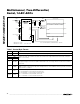
INPUT VOLTAGE (LSB)
BINARY OUTPUT CODE (LSB)
0123 16383
V
REF
V
REF
16381
0...000
0...001
0...010
0...011
1...111
1...110
1...101
1...100
1 LSB =
V
REF
16384
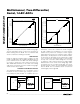
Figure 14. Unipolar Transfer Function
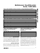
INPUT VOLTAGE (LSB)
TWO'S COMPLEMENT BINARY OUTPUT CODE (LSB)
0123 8191
8192
8193 16383
V
REF
V
REF
16381
1...000
1...001
1...010
1...011
1...111
0...000
0...001
0...111
0...110
0...101
0...100
1 LSB =
V
REF
16384
Figure 15. Bipolar Transfer Function
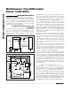
SCLK
DOUT
I/O
SCK
MISO
V
DD
SS
SPI
MAX1146–
MAX1149
CS
Figure 16a. SPI Connections
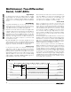
MAX1146–
MAX1149
SCLK
DOUT
I/O
SK
SI
MICROWIRE
CS
Figure 16b. MICROWIRE Connections