
Instruction Manual


MAX11300PMB1 Peripheral Module and Munich (USB2PMB1) Adapter Board Quick Start Guide
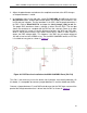
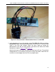
Figure 33. The Width of a PWM Is Adjusted by a Potentiometer
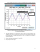
1. In the drop-down menu at the top right, select P4_DAC_0V>+10V and click the Get plot
box button. Another plot window opens for DAC on P4. Click on Read DAC File in the
newly opened P4_DAC window and open the analog data point
file ideal_sawtooth_right_1000_3x.adc.
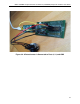
2. Connect a potentiometer cable assembly to Port 4 (black jumper wire), Port 14 (red
jumper wire), and GND (black jumper wire). Connect Port 3 to Port 13 (yellow
jumper wire) as shown in Figure 34 and Figure 35.
31