
Instruction Manual


MAX11300PMB1 Peripheral Module and Munich (USB2PMB1) Adapter Board Quick Start Guide
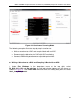
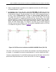
Figure 27. Sine Wave with 170µs Sample Delay
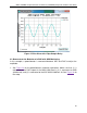
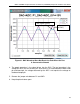
6.2 Demonstrate the Behavior of a DAC with ADC Monitoring
In this example, a potentiometer is connected between ADC and DAC to adjust the
amplitude.
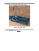
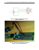
1. See Figure 28 for the potentiometer schematic connection. Make sure that (1) is
connected to the DAC output of the MAX11300 Port 0, (2) is connected to GND
(middle row), and (3) is connected to the ADC MAX11300 Port 10. See
Figure 29 for
the setup.
26