
Instruction Manual


MAX11300PMB1 Peripheral Module and Munich (USB2PMB1) Adapter Board Quick Start Guide
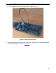
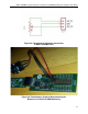
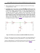
3. Use a jumper wire to connect P0 to P10 as shown in Figure 25.
Figure 25. P0 Connected to P10
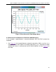
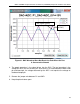
4. After connecting the DAC to the ADC, observe a sine-wave-like-shaped waveform in
the ADC plot window as shown in Figure 26
.
24