
Instruction Manual


MAX11300PMB1 Peripheral Module and Munich (USB2PMB1) Adapter Board Quick Start Guide
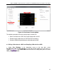
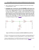
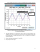
Figure 22. Continuous Scanning Mode
The following examples illustrate step-by-step instructions to:
• Write a waveform to a DAC and sample it back with an ADC.
• Demonstrate the behavior of a DAC with ADC monitoring.
• Generate PWM with potentiometer-adjustable pulse width.
6.1 Writing a Waveform to a DAC and Sampling It Back with an ADC
1.
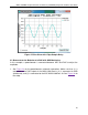
Under Plot Windows in the drop-down menu at the top right, select
P0_DAC_0V>+10V and Get plot box. A small plot window appears on the screen as
shown in Figure 23
. Click Read DAC File and select an analog data point file called
ideal_sine_1000_3x.adc.
22