
Instruction Manual

MAX11300PMB1 Peripheral Module and Munich (USB2PMB1) Adapter Board Quick Start Guide
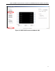
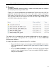
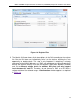
Figure 16. MAX11300PMB1/Munich Connected to PC Through a USB Cable
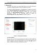
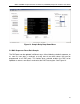
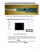
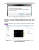
Figure 17. Munich GUI at Startup
3. Click the Connect button. The Munich GUI then reads the current
configuration from the connected MAX11300PMB and displays the pin
description for each pin. If the device is powered up, every pin is high-Z (high
impedance) as shown in Figure 17.
4. Under Configuration, click on Read from File and select the register file
MAX11300Register_Demo.csv as shown in Figure 18.
HIGH-Z AT STARTUP
18